
Hard-top convertible roof system

a convertible roof and hard-top technology, applied in the direction of roofs, engine seals, vehicle components, etc., can solve the problems of difficult to tightly nest together roof sections, packaging and assembly obstacles in the typically tight confines of the vehicle body, etc., to reduce the storage area of roof packaging and reduce the cost of assembly.

Inactive Publication Date: 2005-03-15
SPECIALTY VEHICLE ACQUISITION
View PDF133 Cites 22 Cited by
  • Summary
  • Abstract
  • Description
  • Claims
  • Application Information

AI Technical Summary

Benefits of technology

The hard-top convertible roof system of the present invention is advantageous over conventional systems in that the present invention minimizes the stored roof packaging area by tightly collapsing one roof section relative to the other. The present invention convertible roof system is also advantageous by employing a relatively powerful and easy to package linkage mechanism that allows for collapsing of the relatively heavy hard-top roof sections with minimal, if any, intrusion on the passenger compartment area of the vehicle while also storing the roof forward of a user accessible storage area, such as a trunk or pickup truck bed. Furthermore, the present invention does not require as great a centerline opening for the roof storage area as do many traditional hard and soft-top convertible roofs. The convertible roof system of the present invention is also simpler and less costly to assemble to the vehicle body since fewer body attachment points are used. Additional advantages and features of the present invention will become apparent from the following description and appended claims, taken in conjunction with the accompanying drawings.

Problems solved by technology

Most convertible hard-top roofs, however, employ a complicated linkage arrangement to couple the forwardmost hard-top roof section to either the vehicle body or the rear hard-top roof section.
This is often due to the weight and moment-arm effect of the front roof section during retraction.
For example, many of these known mechanisms use an elongated balance link coupling the body to the front roof section, or an elongated sliding or track guide secured to the vehicle body and coupled to a link; notwithstanding, such mechanisms may pose packaging and assembly obstacles in the typically tight confines of the vehicle body.
Additionally, many of these traditional roof sections are difficult to tightly nest together in a stowed position in order to minimize the convertible roof storage space in the vehicle.

Method used


Image

  • Hard-top convertible roof system
  • Hard-top convertible roof system
  • Hard-top convertible roof system

Examples


Embodiment Construction

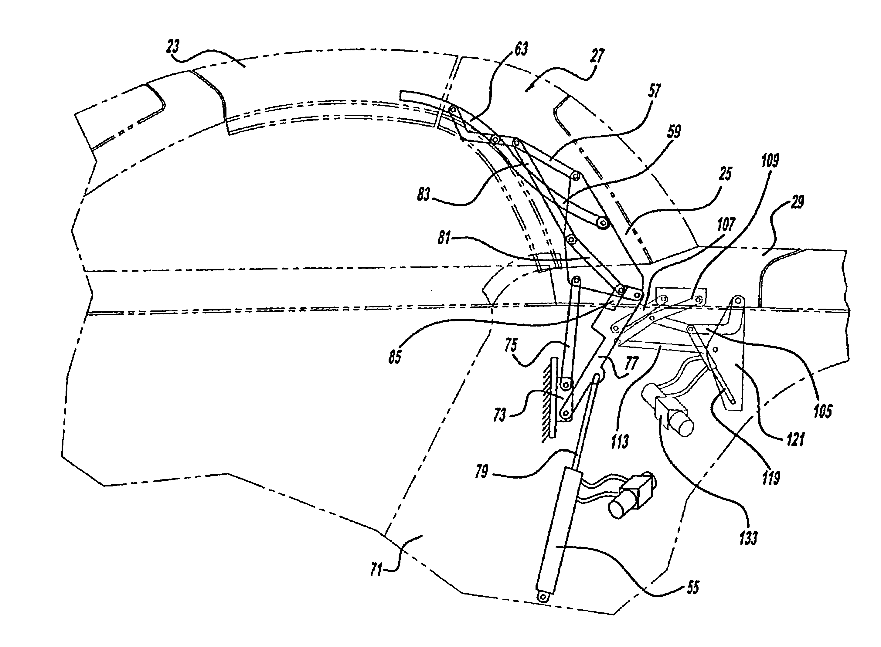
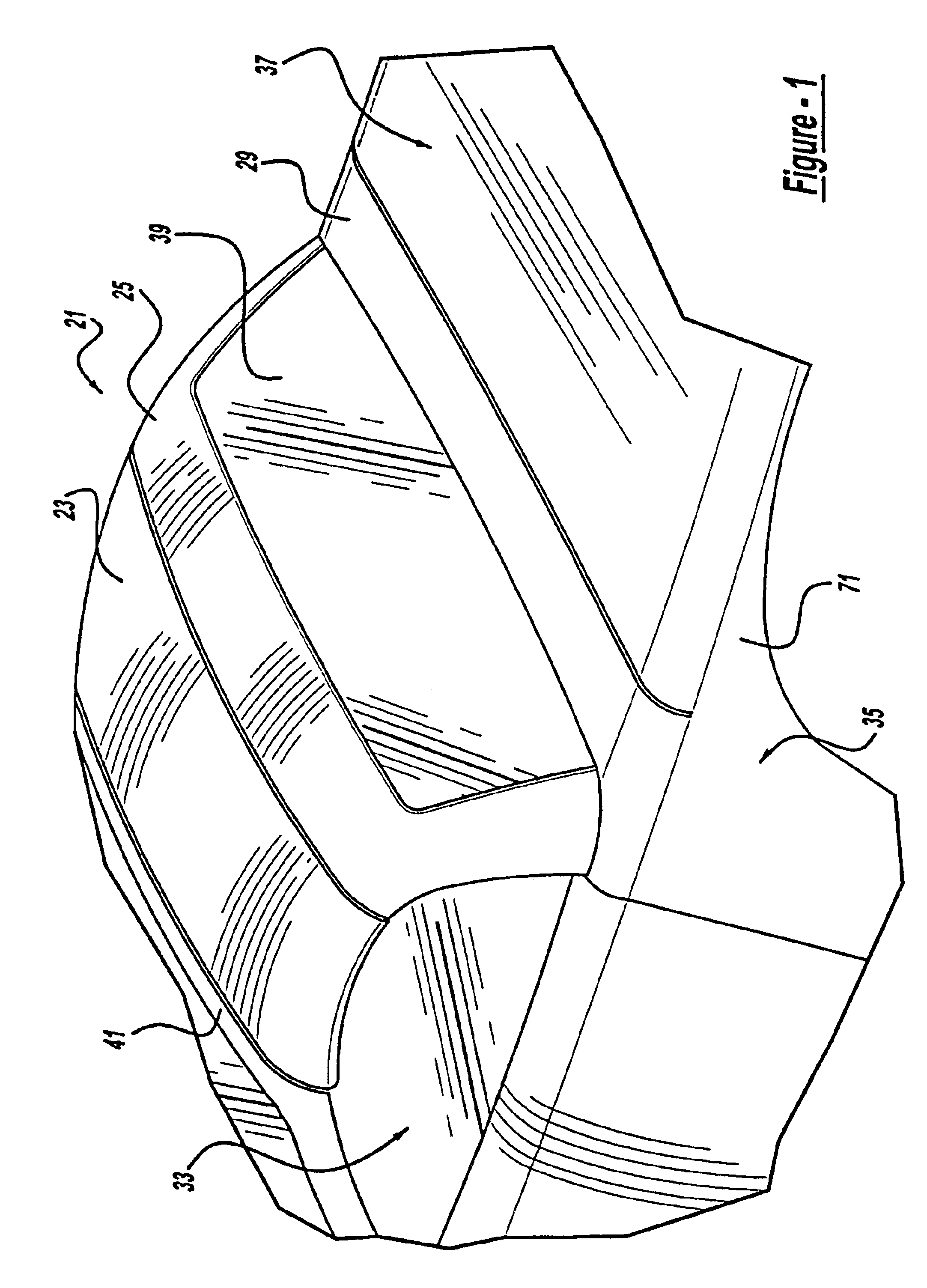
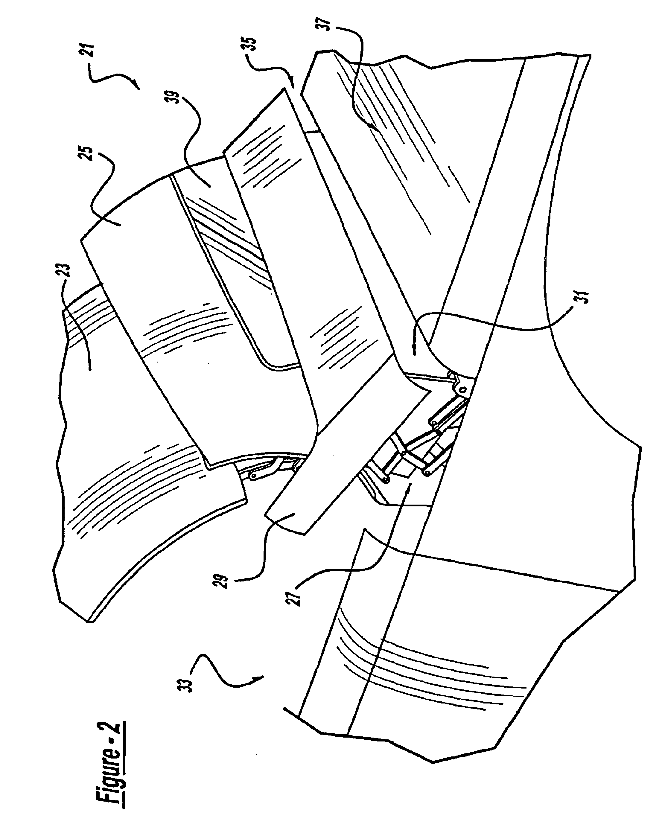
Referring to FIGS. 1-3 and 10, a convertible roof system 21 is part of an automotive vehicle and includes a hard-top front roof 23, a hard-top rear roof 25, a top stack mechanism 27 operable to move the roofs, a rigid tonneau cover 29 and a tonneau cover mechanism 31. Roofs 23 and 25 are automatically movable from fully raised and closed positions covering a passenger compartment 33, as shown in FIG. 1, to fully retracted and open positions, as shown in FIGS. 3 and 10, wherein roofs 23 and 25 are stowed in a roof storage area or compartment 35. Roof storage compartment 35 is located between and physically separated by metal panels 36 (see FIG. 9) from passenger compartment 33 and an externally accessible storage area for miscellaneous articles such as a trunk or pickup truck bed 37. A rigid, glass back window or backlite 39 is secured to rear roof 25 while front roof 23 is disengagably attached to a front header panel 41 by latches. Weatherstrips or seals are also employed around th...


PUM


Abstract

A convertible roof system includes a front roof section, a rear roof section, an automatically power actuator and a linkage mechanism. In another aspect of the present invention, the front and / or rear roof sections are rigid, hard-top roofs. A further aspect of the present invention provides that the outside surfaces of the roofs have a generally vertical orientation when in their open and retracted positions.

Description

BACKGROUND AND SUMMARY OF THE INVENTIONThis invention relates generally to automotive roof systems and more particularly to a convertible roof system for an automotive vehicle.Rigid hard-top convertible roofs have been used on a variety of automotive vehicles. Some of these conventional convertible hard-top roofs are stored in a generally vertical orientation and some are stored in a predominantly horizontal orientation. Furthermore, some of these conventional hard-top roofs fold in a clamshelling manner while others are collapsible in an overlapping manner. Most convertible hard-top roofs, however, employ a complicated linkage arrangement to couple the forwardmost hard-top roof section to either the vehicle body or the rear hard-top roof section. This is often due to the weight and moment-arm effect of the front roof section during retraction. For example, many of these known mechanisms use an elongated balance link coupling the body to the front roof section, or an elongated slidi...

Claims


Application Information

Patent Timeline
Patent Type & Authority Patents(United States)
IPC IPC(8): B60J7/14B60J7/08
CPCB60J7/148B60J7/146
Inventor WILLARD, MICHAEL T.
Owner SPECIALTY VEHICLE ACQUISITION
Learn More