
Method for compensating mild lateral velocity variations in pre-stack time migration in the frequency-wave number domain

a pre-stack time migration and frequency-wave number technology, applied in the field of seismic prospecting, can solve the problems of unmigration seismic image seismic reflections appearing at incorrect locations, data interpretation stage cannot be successful, and prestack migration is generally much more expensive than poststack migration

Inactive Publication Date: 2005-03-08
EXXONMOBIL UPSTREAM RES CO
View PDF2 Cites 32 Cited by
  • Summary
  • Abstract
  • Description
  • Claims
  • Application Information

AI Technical Summary

Benefits of technology

FIG. 8A illustrates a more comp

Problems solved by technology

Obviously, the data interpretation stage cannot be successful unless the processed seismic data provide an accurate representation of the subsurface geology.
The need for seismic migration arises because variable seismic velocities and dipping reflectors cause seismic reflections in unmigrated seismic images to appear at incorrect locations.
However, prestack migration is generally much more expensive than poststack migration.
Accordingly, the use of prestack migration has typically been limited to situations where poststack migration does not provide an acceptable result, e.g., where the reflectors are steeply dipping.
Both vertical time and lateral position errors occur in time migration whenever there are lateral velocity variations in the subsurface.
However, there is no known way to treat mild lateral velocity variations in the Fourier domain similar to the methods used in the space domain.
These lateral velocity variations are usually big enough to cause errors, particularly in the lateral position of steeply dipping reflectors, when the traditional PSTM is applied using a single laterally-invariant velocity function.
However it is far more expensive than PSTM.
It can not correct the lateral position error.
It can not focus diffraction energy correctly.
Therefore, it will loose the sharpness of fault images and give incorrect reflector dips (Bevc, 1995).

Method used


Image

  • Method for compensating mild lateral velocity variations in pre-stack time migration in the frequency-wave number domain
  • Method for compensating mild lateral velocity variations in pre-stack time migration in the frequency-wave number domain
  • Method for compensating mild lateral velocity variations in pre-stack time migration in the frequency-wave number domain

Examples


examples

Three examples are given below to demonstrate the effectiveness of the present inventive method for correcting errors in both lateral position and vertical time in PSTM in the wave number and frequency domain. Each example applies a standard procedure in wide use for testing the accuracy of seismic processing algorithms.

(1) Impulse Response Test:

The first example is an impulse response test for a velocity model with a dipping water bottom in two-dimensional space. FIG. 2 illustrates this velocity model. The water bottom 21 has a dip of about 3 degrees. The vertical axis is depth in meters and the horizontal axis is distance x in meters. The water depth ranges from 1500 m at the left end to 500 m at the right. The sediment velocity function is assumed to be given by the following linear function of depth :

v()=1600+0.4(−ωb)  (13)

where ωb is the water depth in meters. Because the water bottom is slightly dipping (approximately 3 degrees), ωb depends on horizontal position x, and there...


PUM


Abstract

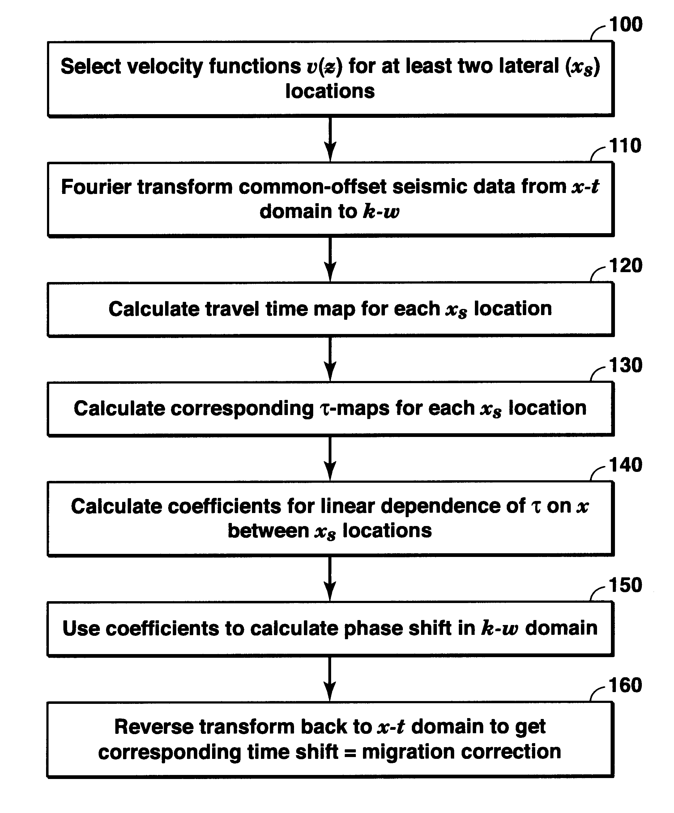
A method for performing pre-stack time migration of seismic data in a region where the subsurface seismic wave propagation velocity varies in both the vertical direction and a horizontal direction. The migration is performed in the wave number—frequency domain and involves using travel time maps to find a linear fitting of the migration phase shift for a given ray parameter and at a given vertical depth versus horizontal position. The slope and intercept parameters from the linear fit are used to adjust a known pre-stack time migration equation, with the accuracy of the linear approximation requiring mild horizontal velocity variation.

Description

FIELD OF THE INVENTIONThis invention relates generally to the field of seismic prospecting and, more particularly, to imaging of seismic data. Specifically, the invention is a method for prestack time migration of seismic data where the velocity function has mild lateral variation.BACKGROUNDIn the oil and gas industry, seismic prospecting techniques are commonly used to aid in the search for and evaluation of subterranean hydrocarbon deposits. A seismic prospecting operation consists of three separate stages: data acquisition, data processing, and data interpretation. The success of a seismic prospecting operation is dependent on satisfactory completion of all three stages. Petroleum engineers know how to produce hydrocarbons from reserves found by a successful prospecting operation.In the data acquisition stage, a seismic source is commonly used to generate a physical impulse known as a “seismic signal” that propagates into the earth and is at least partially reflected by subsurfac...

Claims


Application Information

Patent Timeline
IPC IPC(8): G01V1/28
CPCG01V1/28G01V2210/51
Inventor JING, CHARLIE
Owner EXXONMOBIL UPSTREAM RES CO
Learn More