Optical transmission method, optical transmitter, optical receiver, and optical transmission system

a transmission method and optical technology, applied in the direction of transmission, electromagnetic transmission, electrical equipment, etc., can solve the problems of chromatic dispersion interference between encoded signals, limited transmittable distance, and considerable intersymbol interference due to chromatic dispersion, etc., to achieve the widest dispersion tolerance, the effect of sufficient tolerance and long transmission path

Inactive Publication Date: 2005-03-08
NIPPON TELEGRAPH & TELEPHONE CORP
View PDF12 Cites 68 Cited by
  • Summary
  • Abstract
  • Description
  • Claims
  • Application Information

AI Technical Summary

Benefits of technology

In consideration of the above circumstances, the present invention relates to an optical transmission system using a partial response encoded signal, and an objective of the present invention is to provide a technique for improving the wavelength tolerance, compensating the dispersion in a simple way, and reducing the limitation of the fiber input power.
As shown in FIG. 43, according to the present invention, it is possible to provide an optical transmission system having (i) the widest dispersion tolerance in the practical range of the fiber input power, and (ii) a fixed optimum dispersion with respect to a variation in the practical range of the fiber input power. That is, the optical transmission system (having an optical transmitter and an optical receiver) according to the present invention has a sufficient tolerance with respect to the degradation of the transmitting quality due to the interaction between the nonlinear optical effects and the chromatic dispersion of the transmission medium. Accordingly, it is possible to construct an optical transmission system having a longer transmission path, a larger transmittable capacity, and much more reliability in comparison with conventional optical transmission systems using an optical duobinary encoded signal, NRZ encoded signal, RZ encoded signal, or the like.

Problems solved by technology

Therefore, if the optical input power increases, marked waveform distortion appears due to interaction between the self phase-modulation effect and the chromatic dispersion, and thus the tolerance characteristics of the chromatic dispersion are degraded.
Therefore, if dispersion compensation is performed under the simple condition of “D=0”, considerable intersymbol interference due to the chromatic dispersion may occur between the encoded signals in the receiver because the optimum value of the dispersion compensation is shifted from that point.
Therefore, the effect of the chromatic dispersion or a dispersion slope cannot be ignored, so that the transmittable distance may be limited if the transmission speed is increased.
In addition, in the technique of generating the dual-mode beat pulse disclosed in the above Reference 7, it is difficult to synchronize the optical frequencies of two longitudinal modes, so that the stability is inferior.
In other words, the degradation of the transmission quality in such an optical transmission system is caused by an effect of the group velocity dispersion of each optical fiber in the bandwidth of an optical signal.
According to such an effect, the waveform of the optical pulse is deformed and interference between adjacent time slots may occur.
However, when the intensity of light incident on the optical fiber transmission path is increased, the dispersion tolerance of the optical duobinary transmission method is degraded, and in particular, the total dispersion, which is optimum in a low-power region, is considerably degraded in the vicinity of 0 ps / nm.
This is because a frequency chirp is added to the optical signal due to the nonlinear optical effects in the optical fiber, Additionally, the dispersion tolerance itself is very small such as ¼ or ⅛ in comparison with the optical duobinary transmission method; thus, the system design itself is difficult and system optimization is also difficult when the system is introduced into practical use.
This makes the system design complicated and disturbs the speedy introduction and stable operation of the system.
That is, in the design of the optical transmission system, it is necessary to consider the optimum dispersion which varies depending on the fiber input power, and thus the design is complicated.
However, only the dispersion of the optical fiber can be acquired in the above measurement of dispersion; thus, it is difficult to follow the variation of the optimum dispersion specific to each transmission system which employs a specific encoded signal.
Therefore, in the optical transmission system employing a conventional method, the bit rate or transmission distance must be limited.
This prevents the stable operation of the optical transmission system.

Method used


Image

  • Optical transmission method, optical transmitter, optical receiver, and optical transmission system
  • Optical transmission method, optical transmitter, optical receiver, and optical transmission system
  • Optical transmission method, optical transmitter, optical receiver, and optical transmission system

Examples


first embodiment

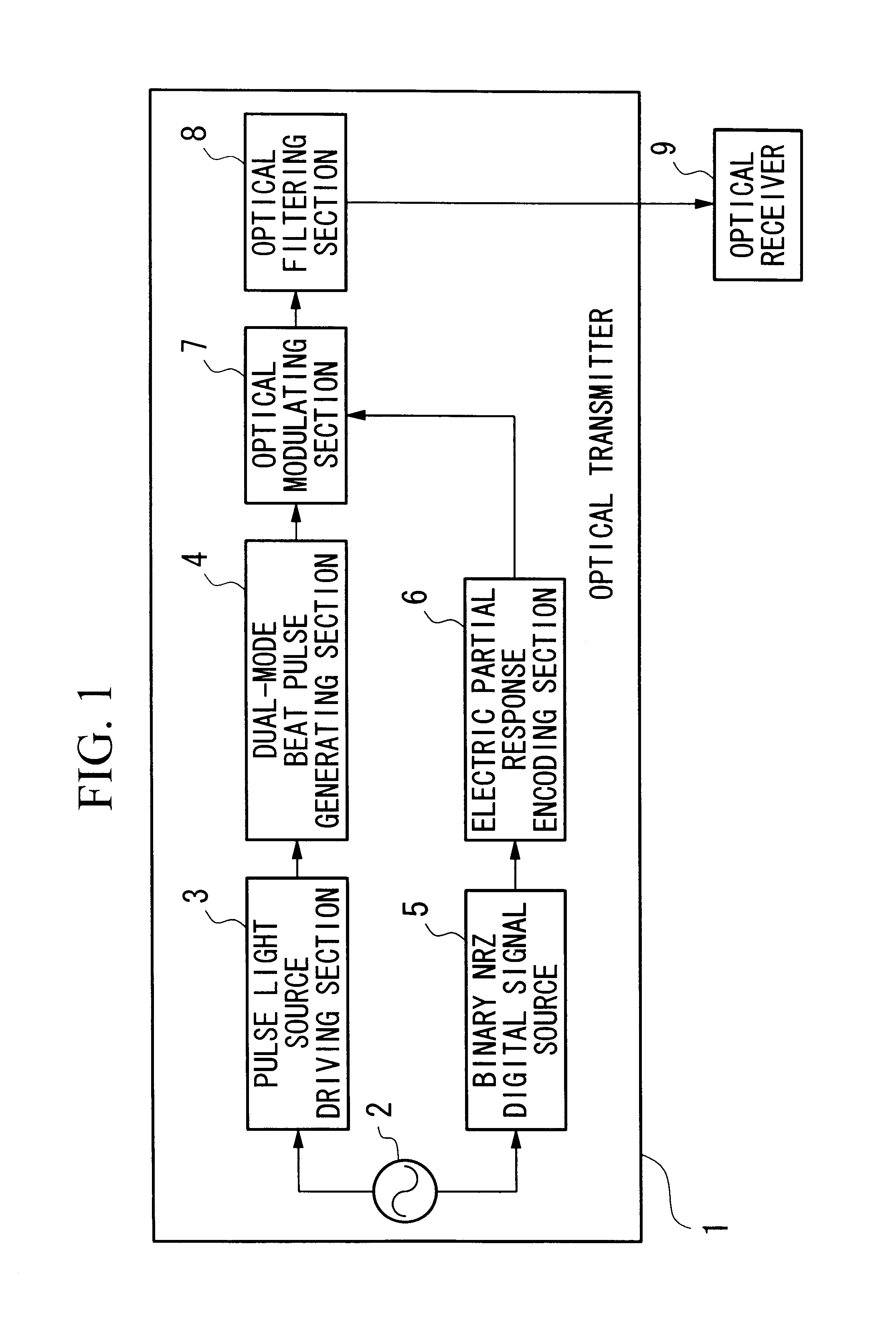
FIG. 1 is a block diagram showing the general structure of the optical transmission system as a first embodiment of the present invention. Reference numeral 1 indicates an optical transmitter, reference numeral 2 indicates a system clock source, reference numeral 3 indicates a pulse light source driving section, reference numeral 4 indicates a dual-mode beat pulse generating section, reference numeral 5 indicates a binary NRZ digital signal source, reference numeral 6 indicates an electric partial response encoding section, reference numeral 7 indicates an optical modulating section, reference numeral 8 indicates an optical filtering section, and reference numeral 9 indicates an optical receiver.

As shown in FIG. 1, the optical transmission system according to the present embodiment has the optical transmitter 1 for transmitting an optical signal modulated using an electric partial response encoded signal, and the optical receiver 9 for receiving the optical signal transmitted from t...

example 1

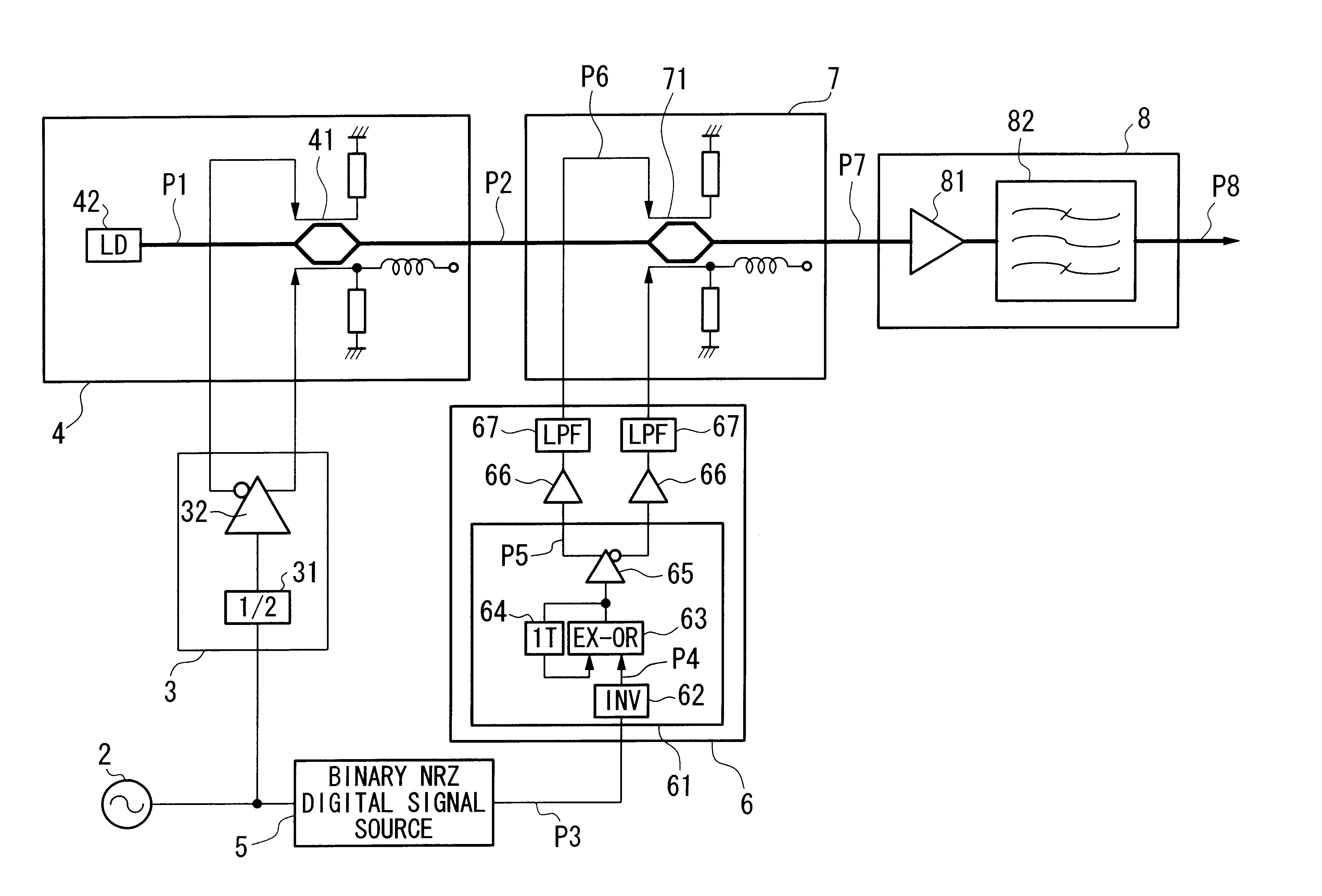
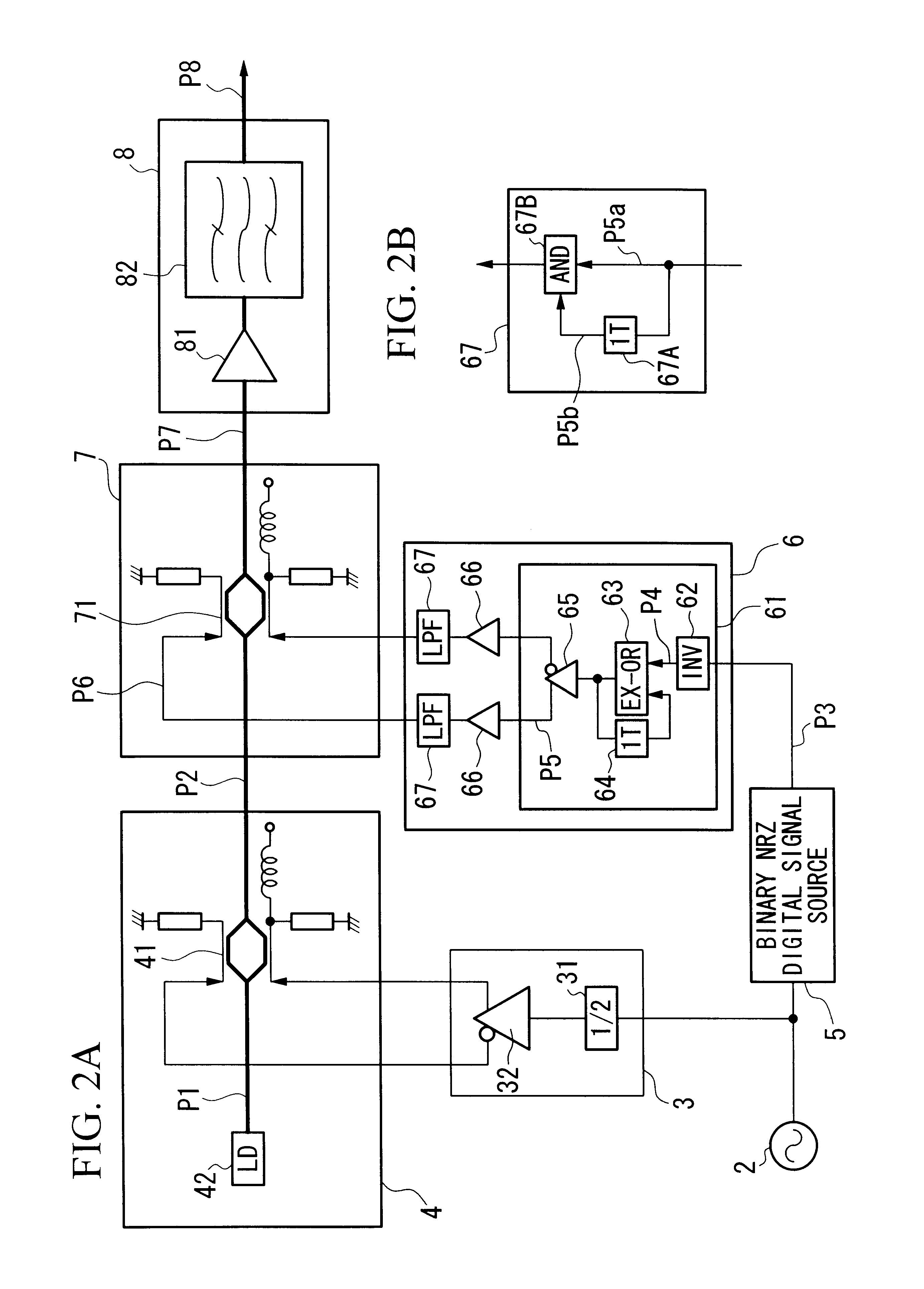
FIGS. 2A and 2B are block diagrams showing the general structure of the optical transmitter as a first example.

In the figures, reference numeral 2 indicates a system clock source, reference numeral 3 indicates a pulse light source driving section, reference numeral 31 indicates a ½ frequency-dividing circuit, and reference numeral 32 indicates a drive circuit.

Reference numeral 4 indicates a dual-mode beat pulse generating section, reference numeral 41 indicates an MZ (Mach-Zehnder) optical intensity modulator, and reference numeral 42 indicates a CW (continuous wave) laser (light) source.

Reference numeral 5 indicates a binary NRZ digital signal source, reference numeral 6 indicates an electric partial response encoding section, reference numeral 61 indicates a pre-coder, reference numeral 62 indicates a logical inversion circuit, reference numeral 63 indicates an exclusive OR (EX-OR) circuit, reference numeral 64 indicates a 1-bit delay circuit, reference numeral 65 indicates a diff...

second embodiment

EXAMPLE 1

FIG. 22 is a block diagram showing the general structure of a first example of the optical transmission system (an optical transmitter and an optical receiver) in the second embodiment according to the present invention.

In the figure, the present optical transmission system comprises an optical transmitter 101 for converting an optical duobinary encoded signal into a carrier-suppressed RZ optical duobinary encoded signal and transmitting the converted signal, and an optical receiver 102 for receiving the carrier-suppressed RZ optical duobinary encoded signal transmitted via an optical transmission medium 103 while dividing the bands of the received signal.

The optical receiver 101 comprises an optical duobinary encoded signal generating section 170 for generating a known optical duobinary encoded signal, and an optical modulating section 110 for converting the generated optical duobinary encoded signal into a carrier-suppressed RZ optical duobinary encoded signal by adding a...


PUM


Abstract

A system which improves wavelength tolerance, compensates dispersion in a simple way, reduces limitation of the fiber input power is disclosed. The operation includes receiving a clock signal from a system clock source; modulating a single mode optical signal based on the clock signal and generating an optical pulse signal having two longitudinal modes, the frequency interval thereof being n×B, n being a natural number and B being a transmission speed; generating a partial response signal by converting a binary NRZ signal from a digital signal source in synchronism with the system clock source; and modulating the optical pulse signal based on the partial response signal, and outputting a binary RZ modulated signal. The binary RZ modulated signal is input into a receiver, where two partial response components in the optical spectra of the input signal are divided, and one or both of the components are received.

Description

BACKGROUND OF THE INVENTION1. Field of the InventionThe present invention relates to a system and method of transmitting an optical signal of a single wavelength or a wavelength-division multiplexed optical signal, and in particular, to a technique which is effectively applied to an optical transmission system for modulating an optical signal by using a partial response encoded signal. The present invention also relates to an optical transmission system for suppressing the degradation of the transmitting quality due to chromatic dispersion of a transmission medium such as an optical fiber, or to interaction between the chromatic dispersion and the nonlinear optical effects in the transmission medium. The present invention also relates to an optical transmitter and optical receiver which constitute the optical transmission system.2. Description of the Related ArtIn conventional optical fiber transmission systems, various kinds of encoded signals for modulation have been proposed for ...

Claims


Application Information

Patent Timeline
IPC IPC(8): H04B10/155H04B10/152H04B10/50H04B10/508
CPCH04B10/505H04B10/508H04B10/5055H04B10/5051
Inventor MIYAMOTO, YUTAKAHIRANO, AKIRAYONENAGA, KAZUSHIGESATO, KENJITOBA, HIROMUMATSUURA, AKIHIKO
Owner NIPPON TELEGRAPH & TELEPHONE CORP
Why Eureka
Try Eureka