Loudspeaker diaphragm

a technology of speaker diaphragm and diaphragm, which is applied in the direction of diaphragm, transducer diaphragm, fibre diaphragm, etc., can solve the problems of reducing the quality of radiation sound, reducing the efficiency of sound radiation, and reducing the mechanical strength of the speaker diaphragm over the whole area. , to achieve the effect of reducing the air pressure to the central area, improving the quality of sound

Inactive Publication Date: 2005-03-08
JVC KENWOOD CORP A CORP OF JAPAN
View PDF11 Cites 14 Cited by
  • Summary
  • Abstract
  • Description
  • Claims
  • Application Information

AI Technical Summary

Benefits of technology

The projection extending radially in the slanted area curves along the circumferential direction as the speaker diaphragm comes near to the edge portion. While the speaker diaphragm vibrates at a large amplitude and the central area and the slanted area move toward the bottom side, a force along the circumferential direction can be applied to air which is likely to concentrate upon the central area, so that the air can be rotated. An air pressure to the speaker diaphragm can be lowered so that the quality of radiation sounds can be improved.
One surface in an area from each projection to each recess preferably has a bent portion. The mechanical strength of the speaker diaphragm along the radial direction can therefore be increased to suppress division vibrations and improve the quality of radiation sounds.
The odd number of projections as counted along the circumferential direction are preferably formed, and the projection has preferably a cross section like a screw propeller. Division vibrations having nodes in the radial direction can be forcibly suppressed and the quality of radiation sounds can be improved.
A bottom area of each recess is preferably made thicker than another area. Generation of division vibrations in the slanted area can be forcibly suppressed and the quality of radiation sounds can be improved.
According to the present invention, a force along the circumferential direction is applied to air which is likely to flow toward the central area, so that the air pressure to the central area can be lowered. Sounds can be efficiently radiated and the quality of sounds can be improved.
The speaker diaphragm is preferably manufactured by ejection molding of material containing polypropylene as a main composition. The speaker diaphragm having a characteristic structure can be manufactured easily. By using a variety of colors, an excellent outer appearance with a visually strong impression can be provided.

Problems solved by technology

Therefore, the mechanical strength of the speaker diaphragm is not efficiently improved over the whole area.
A speaker diaphragm having conventional ribs cannot efficiently suppress division vibrations, particularly division vibrations having nodes along the radial direction.
Therefore, while the speaker diaphragm vibrates at a large amplitude, air is likely to press the central area of the speaker diaphragm, and the motion of the speaker diaphragm is hindered to thereby lower the quality of radiation sounds.
It is not possible to mitigate an air pressure in the central area of the speaker diaphragm.

Method used


Image

  • Loudspeaker diaphragm
  • Loudspeaker diaphragm
  • Loudspeaker diaphragm

Examples


Embodiment Construction

A speaker diaphragm according to an embodiment of the invention will be described with reference to the accompanying drawings.

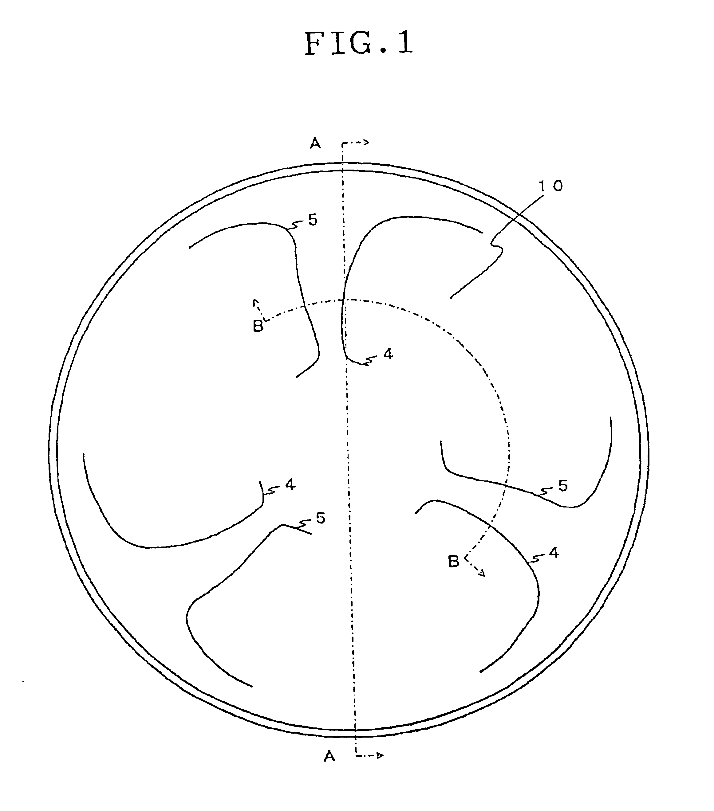
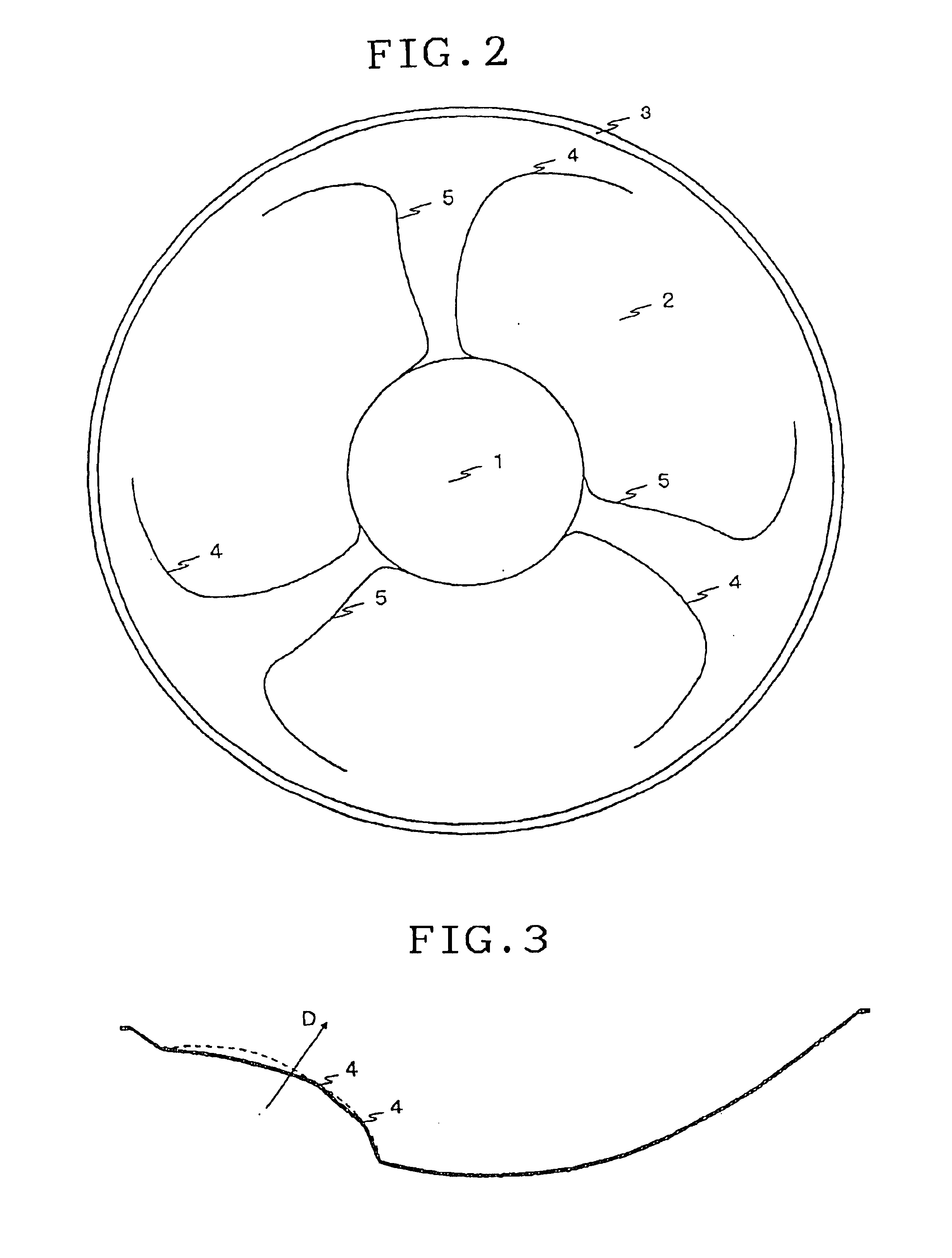
FIG. 1 is a plan view of a speaker diaphragm 10 according to an embodiment of the invention. FIG. 2 is a plan view showing each divided area having a structural difference of the speaker diaphragm 10 so as to facilitate the description relating to the speaker diaphragm 10.

The speaker diaphragm 10 has, for example, a diameter of about 30 cm and can be manufactured by ejection molding of resin containing polypropylene as its main composition. As shown in FIG. 2, the speaker diaphragm 10 is constituted of a central area 1, a slanted area 2, and an edge portion 3.

The central area 1 has a voice coil bobbin, for example, adhered at the bottom thereof and is used as a vibration generation source for vibrating the speaker diaphragm 10.

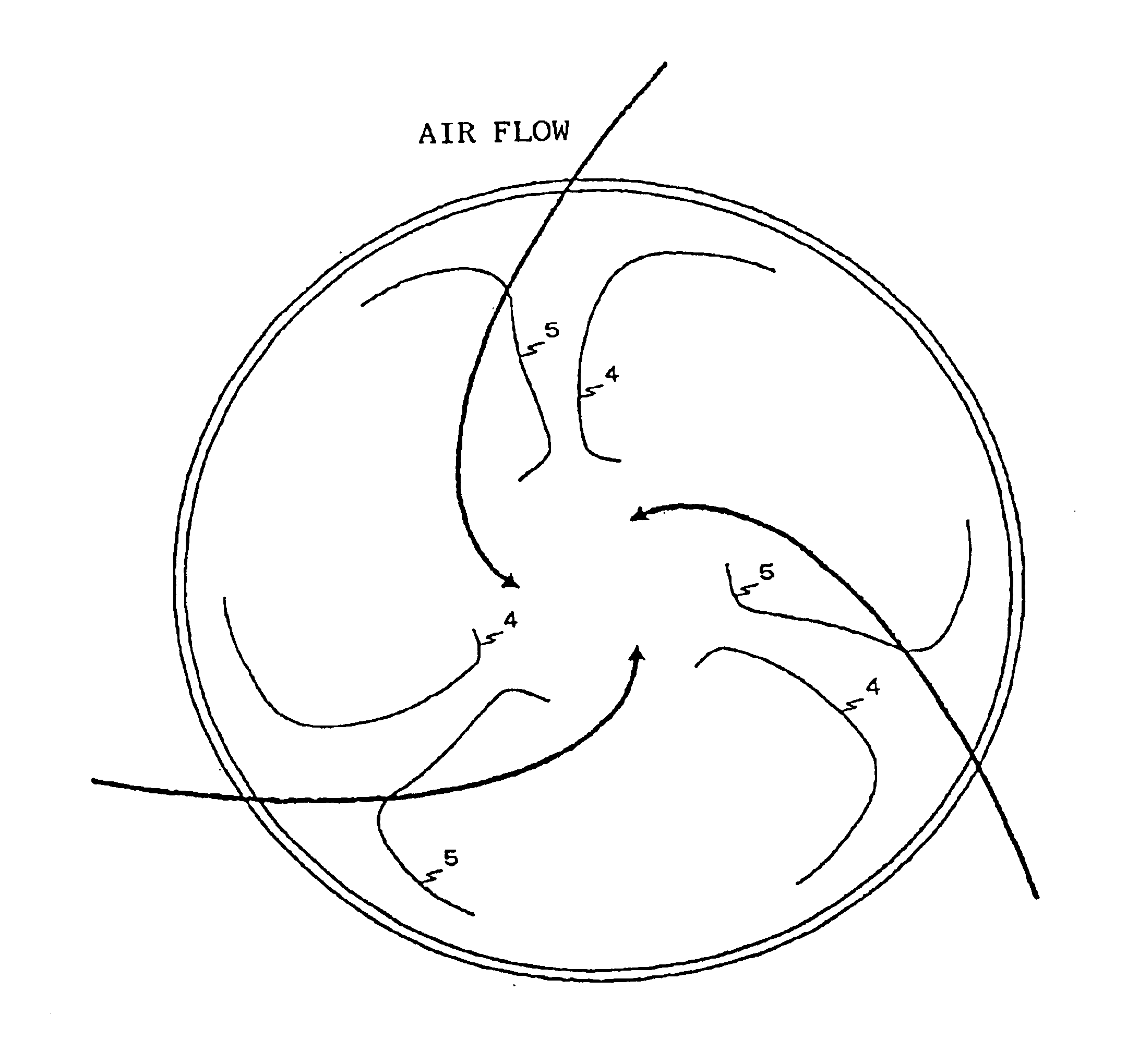
The slanted area 2 propagates vibrations in the central area 1 to peripheral air. As shown in FIG. 1, the slanted area 2 has a plurali...


PUM


Abstract

A speaker diaphragm 10 is provided having an improved quality of radiation sounds and a good outer appearance. The speaker diaphragm has in its slanted area projections typically represented by a peak line 4 and recesses typically represented by a bottom line 5. The projection typically represented by the peak line extends radially from the central area to the edge portion, and curves along the circumferential direction as it comes near to the edge portion. While the speaker diaphragm 10 vibrates at a large amplitude and moves toward the bottom side thereof, a rotation force is applied to air which is likely to concentrate upon the central area to thereby lower the air pressure to the central area. The speaker diaphragm 10 has a three-dimensional structure like a screw propeller so that the mechanical strength of the speaker diaphragm 10 can be increased over the whole area thereof and division vibrations can be suppressed. The speaker diaphragm is manufactured by ejection molding of material containing polypropylene as it main composition so that a variety of colors can be easily used during manufacture processes. In cooperation with the unique structure like the screw propeller, a strong visual impression is given.

Description

FIELD OF THE INVENTIONThe present invention relates to a speaker diaphragm, and more particularly to a speaker diaphragm having a good quality of radiation sounds and an excellent outer appearance.Conventionally, a speaker diaphragm is mechanically reinforced by using ribs or the like. Such ribs are used to prevent distortion of radiation sounds by suppressing generation of division vibrations of the speaker diaphragm and flattening the frequency characteristics.An example of a speaker diaphragm having such ribs is shown in the plan view of FIG. 6.As shown in FIG. 6, this speaker diaphragm is formed with radially disposed projections 30 which are used as ribs. The projections 30 of the speaker diaphragm increases the mechanical strength along the radial direction of the speaker diaphragm to suppress generation of division vibrations having nodes along the circumferential direction.In Japanese Utility Model laid-open No. 2-8249 gazette, a cone type speaker diaphragm integrally formed...

Claims


Application Information

Patent Timeline
IPC IPC(8): H04R7/14H04R7/00
CPCH04R7/14H04R2307/029
Inventor HAYAKAWA, JUNICHIKASAI, MASAYA
Owner JVC KENWOOD CORP A CORP OF JAPAN
Why Eureka
Try Eureka