Methods and circuits for measuring clock skew on programmable logic devices
a programmable logic and clock technology, applied in the direction of heat measurement, instruments, testing circuits, etc., can solve the problems of short delay in network b>110/b>, difficult task of accurately determining clock, etc., and achieve the effect of accurately measuring the skew of clock distribution networks
- Summary
- Abstract
- Description
- Claims
- Application Information
AI Technical Summary
Benefits of technology
Problems solved by technology
Method used
Image
Examples
Embodiment Construction
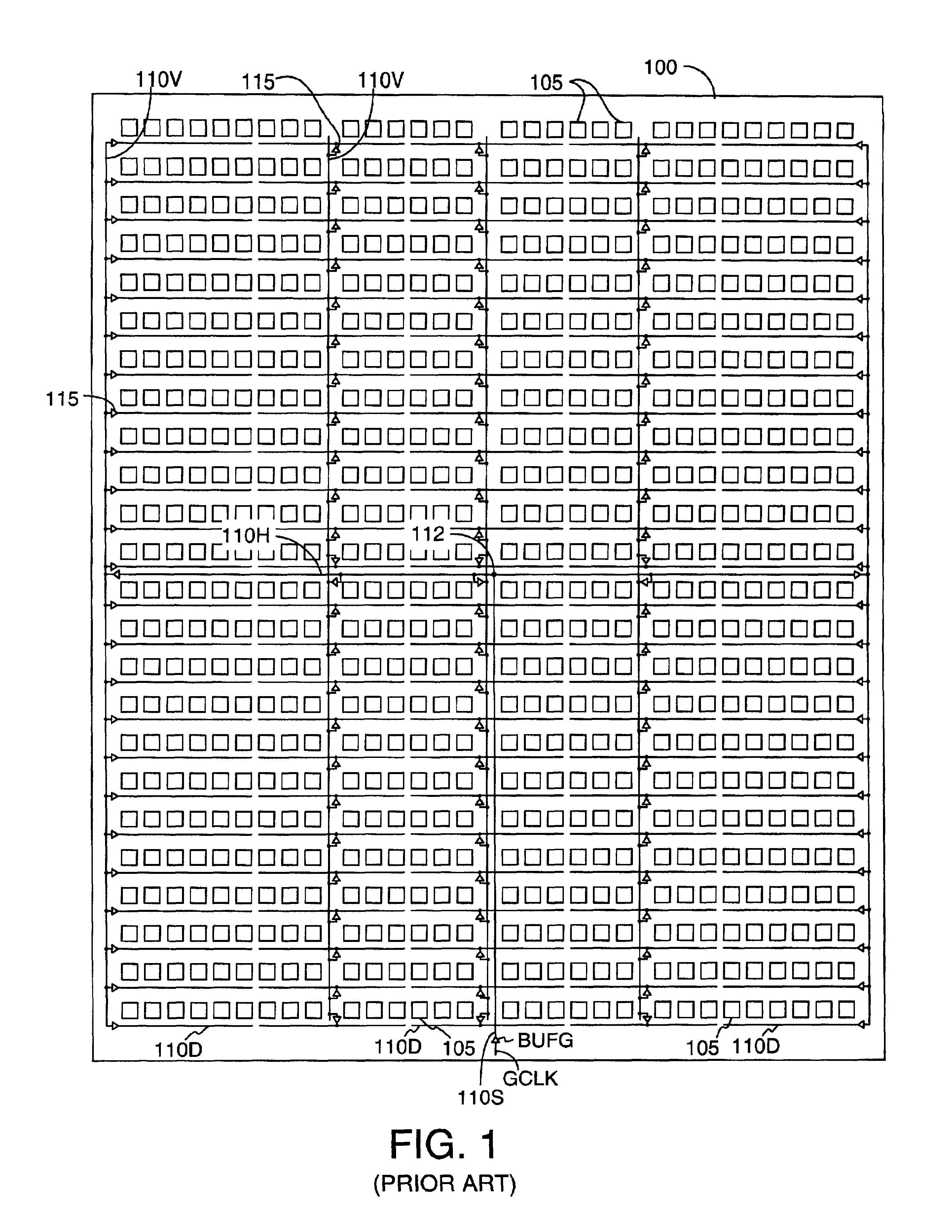
FIGS. 2-5 schematically depict FPGA configurations used in accordance with embodiments of the invention to accurately measure global clock skew for clock distribution network 110 of FIG. 1. In the examples, the FPGA is a Virtex™ XCV1000 FPGA, available from Xilinx, Inc., which includes an array of 96 columns and 64 rows of CLBs, or a total of 6,144 CLBs. The number of CLBs and other FPGA resources shown in the figures is limited for brevity.
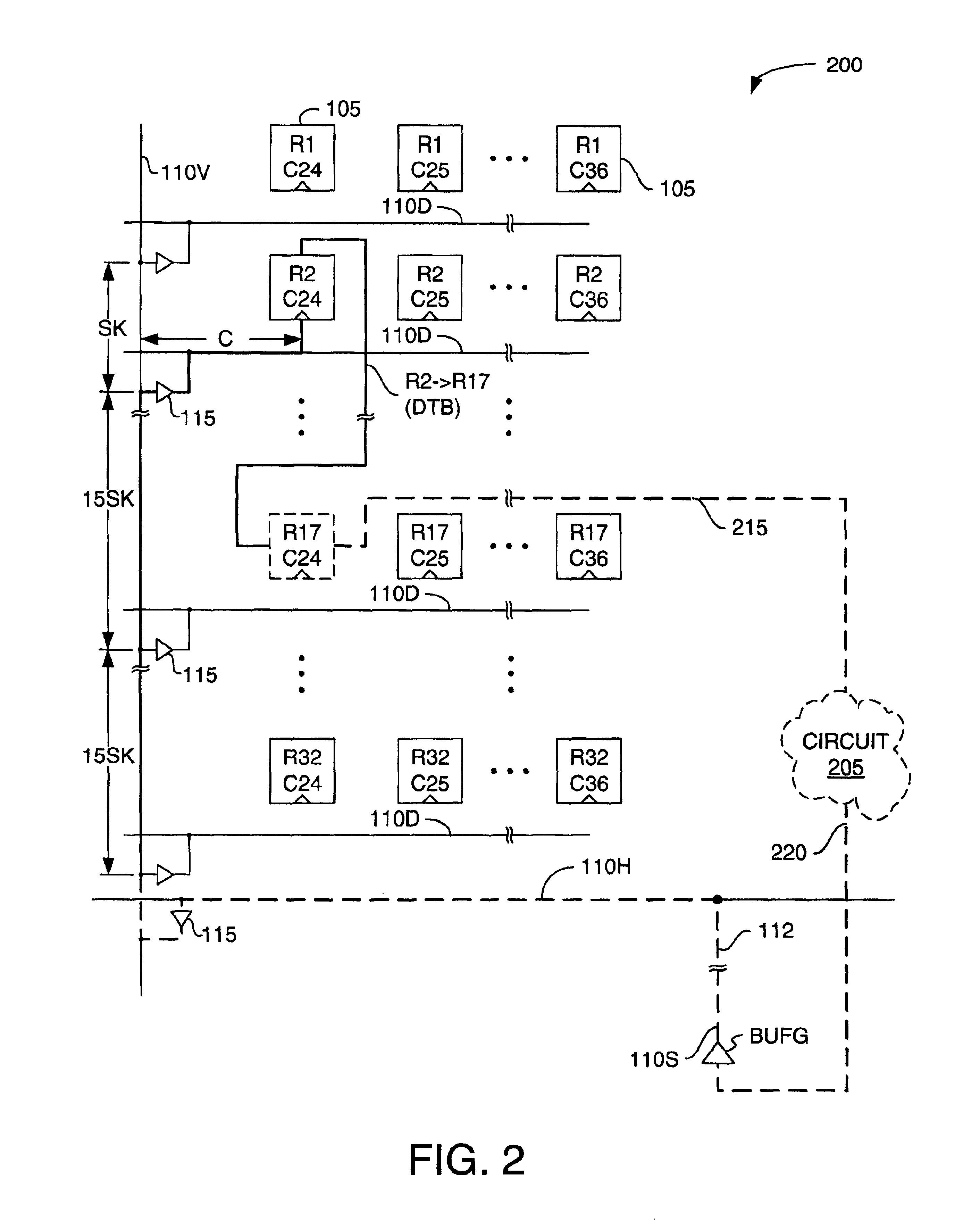
FIG. 2 depicts an FPGA oscillator configuration 200 in which a CLB R2C24 (for row 2, column 24), a CLB R17C24, and a feedback circuit 205 are interconnected to form a ring oscillator. Circuit 205 and the associated connections 215 and 220 are made of available FPGA resources and connect to clock distribution network 110 via global clock buffer BUFG. The resources interconnected as shown using dashed and bold interconnect and clock lines form the ring oscillator.
The FPGA is programmed (i.e., configured) so the global clock buffer BUFG connects to ...
PUM
 Abstract
Description
Claims
Application Information
 - R&D
- Intellectual Property
- Life Sciences
- Materials
- Tech Scout
- Unparalleled Data Quality
- Higher Quality Content
- 60% Fewer Hallucinations
Browse by: Latest US Patents, China's latest patents, Technical Efficacy Thesaurus, Application Domain, Technology Topic, Popular Technical Reports.
© 2025 PatSnap. All rights reserved.Legal|Privacy policy|Modern Slavery Act Transparency Statement|Sitemap|About US| Contact US: help@patsnap.com


