
System and method for accurately characterizing and mapping agricultural plants and foliage

Inactive Publication Date: 2005-03-01
SCHWARTZ ELECTRO OPTICS
View PDF2 Cites 62 Cited by
  • Summary
  • Abstract
  • Description
  • Claims
  • Application Information

AI Technical Summary

Benefits of technology

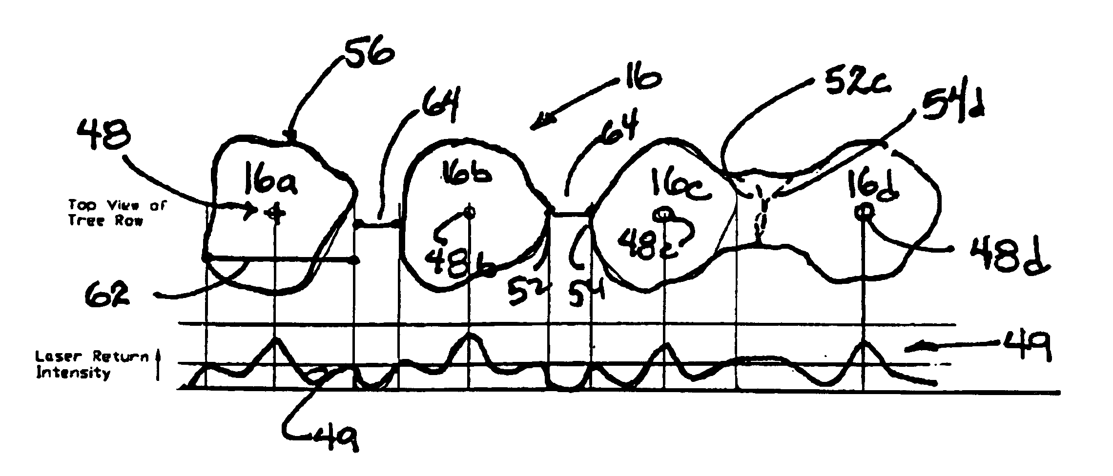
In further describing embodiments of the present invention, various measurements are made to provide the information needed to support proper control of materials distribution and mapping. The center of each tree is located from system measurements for providing the latitude and longitude of the center of trees of interest. A global location is calculated based on a GPS signal, a wheel sensor and a real time clock. The center of the tree is determined based on the range and intensity readings from the sensor measurements as a pulsed laser beam is scanned across a tree. By way of example for one measurement, if a tree is determined to have a spheroidal shaped canopy and is separate from adjacent trees, then the center will be directly measured at the center point between both edges. Attention is also given to trees having other than spheroidal shapes, and trees having little or no foliage. The volume inside the canopy surface of the tree is calculated by numerical integration of the range for each laser pulse fired at the tree. The calculation of foliage density is a relative measurement of the amount of foliage per canopy volume. A tree is divided into a larger grid set of numbers of laser pulses. A grid area within each set is assigned the median intensity of the laser pulses inside that grid. These median intensities are averaged over the entire grid structure and thus the tree. At very close range, intensity of the return pulse may be higher because of reduced laser spot size on a target. A range measurement is used to eliminate effects due to very close range targets. It is expected that modifications will be made to a resulting measurement bas

Problems solved by technology

However, the ever-increasing cost of chemical materials, such as fertilizers, insecticides, herbicides, and the like, as well as the constraints from government authorities regarding their use, has prompted considerable research with a goal of improving the efficiency of agricultural material application.
Further, there is a need to map agricultural fields without the high dependency on weather conditions and the high cost of aerial photography.

Method used


Image

  • System and method for accurately characterizing and mapping agricultural plants and foliage
  • System and method for accurately characterizing and mapping agricultural plants and foliage
  • System and method for accurately characterizing and mapping agricultural plants and foliage

Examples


Embodiment Construction

The present invention will now be described more fully hereinafter with reference to the accompanying drawings, in which embodiments of the present invention are shown by way of illustration and example. This invention may, however, be embodied in many forms and should not be construed as limited to the embodiments set forth herein. Rather, these embodiments are provided so that this disclosure will be thorough and complete, and will fully convey the scope of the invention to those skilled in the art. Like numbers refer to like elements throughout.

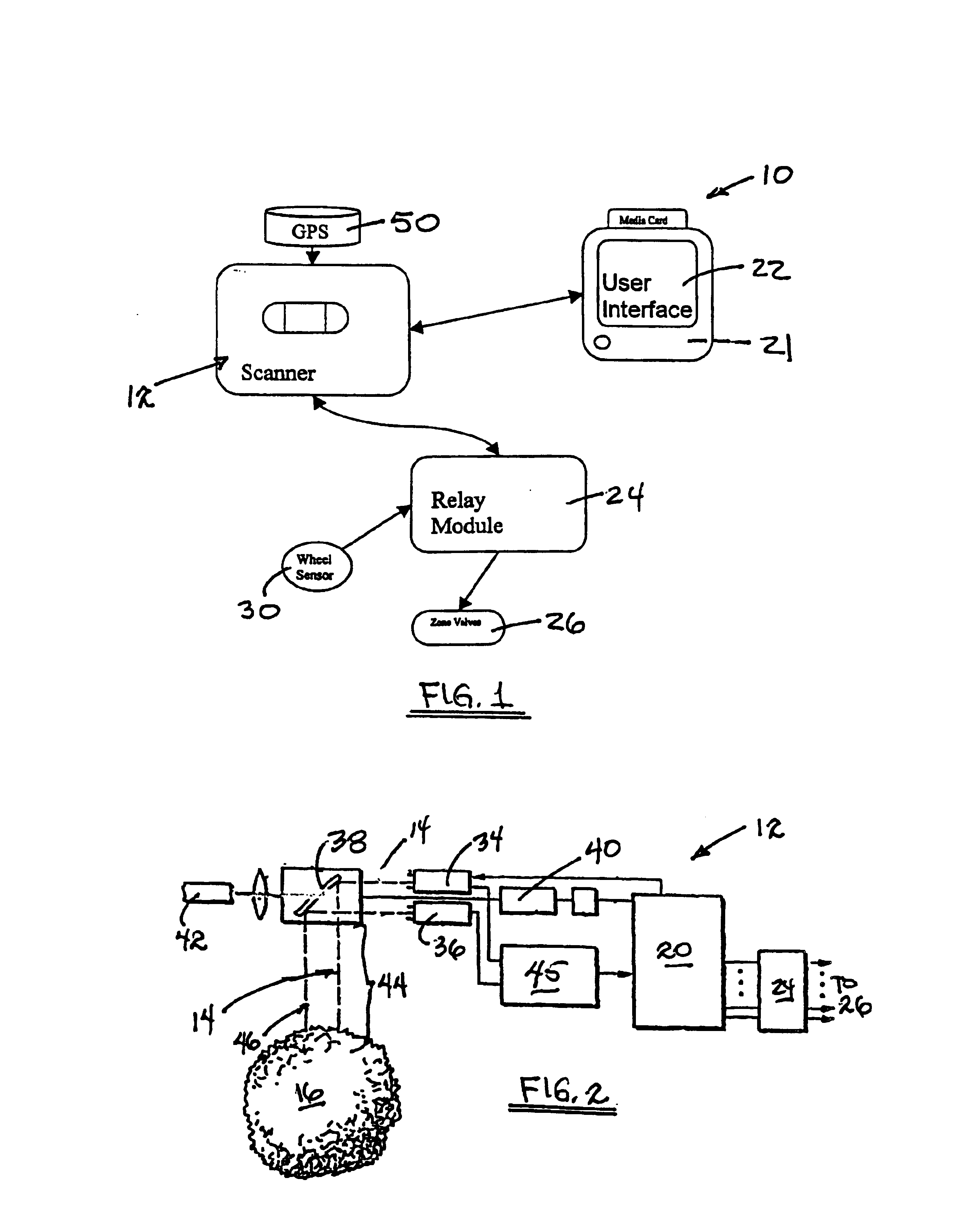
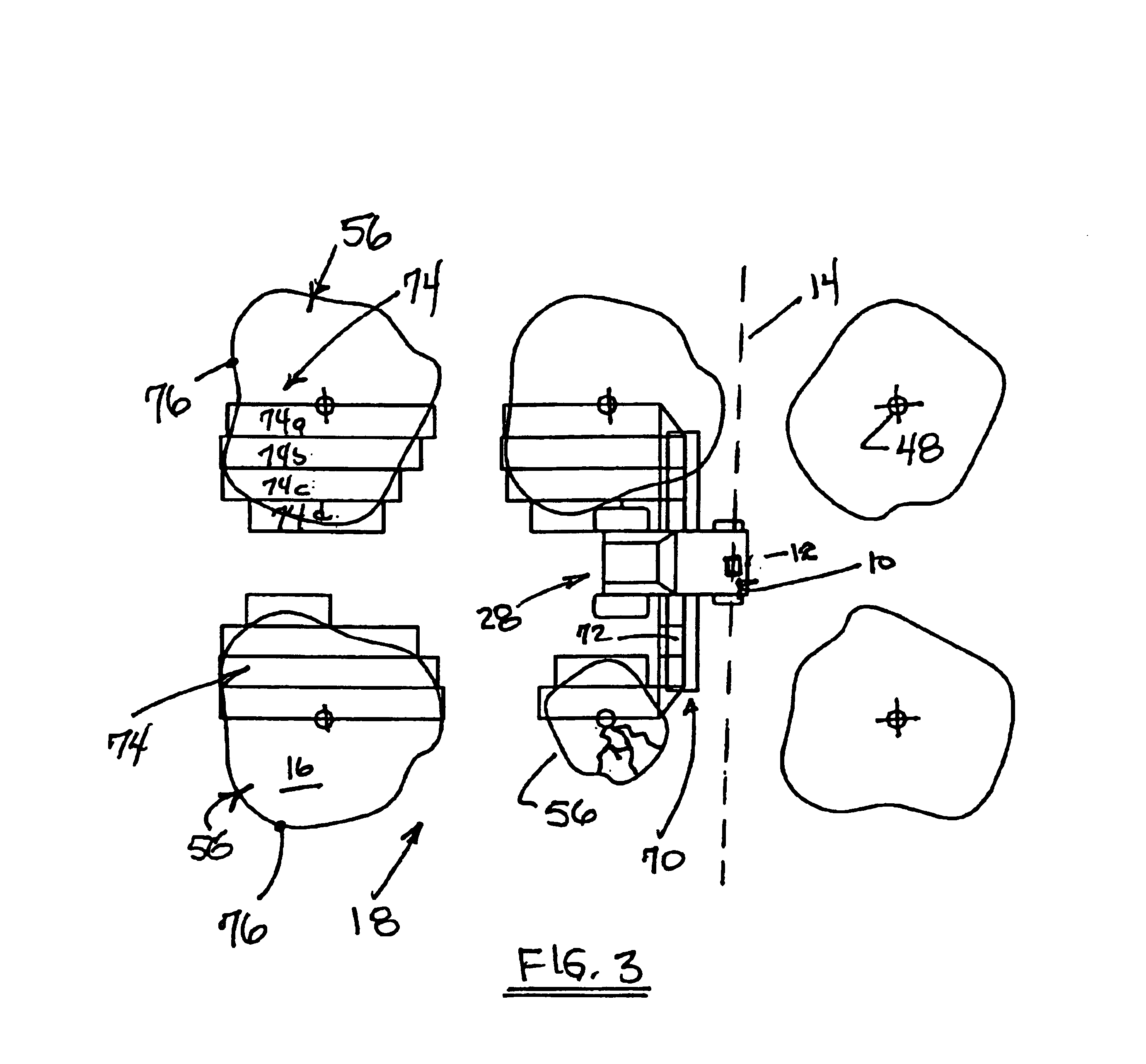
With reference initially to FIG. 1, a system 10 useful in characterizing and mapping agricultural plants and foliage includes a sensor 12 which scans a pulsed laser beam 14 onto each tree 16 within a grove 18, as illustrated with reference to FIGS. 2 and 3, by way of example, for measuring a range or distance to various features of the tree. As herein described for a preferred embodiment of the sensor 12, a laser rangefinder is operable wi...


PUM


Abstract

A lazer rangefinder employs time-of-flight measurements for providing high resolution when measuring range and intensity in a system for accurately mapping and classifying agriculture foliage. Profiles and parameters of the foliage and trees are measured and calculated for classifying the tree, controlling mechanical devices for applying only a pre-selected amount of treatment materials to the tree, and estimating production yeilds. Using a global positioning receiver, a global location for the center of each tree, whether fully grown, juvenile, or dead is identified and used in mapping the measured trees.

Description

FIELD OF THE INVENTIONThe invention generally relates to sensing and physically characterizing objects such as agricultural plants for controlling the application of fertilizers, insecticides, herbicides, and the like, and more particularly to the use of a laser rangefinder for accurately characterizing and mapping the agricultural plants that are typically found in citrus groves and the like.BACKGROUND OF THE INVENTIONThe sensing of agricultural crops including tree foliage for controlling the amount of chemicals to be applied is well known to improve upon the economics of care as well minimizing the adverse impact on the environment. As described in the U.S. Pat. No. 4,823,268 to Giles et al., issued in 1989, tremendous strides have been made in agricultural production. However, the ever-increasing cost of chemical materials, such as fertilizers, insecticides, herbicides, and the like, as well as the constraints from government authorities regarding their use, has prompted conside...

Claims


Application Information

Patent Timeline
IPC IPC(8): G01C3/08G01S17/89A01B79/00A01G1/00G01S7/48G01S17/06G01S17/88
CPCA01B79/005A01G1/00G01S7/4802G01S17/89G01S17/06G01S17/88G01S7/4817
Inventor MCCONNELL, SR., ROBERT E.HOPPENFELD, ROBERT A.TAYLOR, MATTHEW G.
Owner SCHWARTZ ELECTRO OPTICS
Learn More