
Autotransformer-based system and method of current harmonics reduction in a circuit

Inactive Publication Date: 2005-03-01
BALDOR ELECTRIC COMPANY
View PDF14 Cites 38 Cited by
  • Summary
  • Abstract
  • Description
  • Claims
  • Application Information

AI Technical Summary

Benefits of technology

It is in view of the above problems that the present invention is developed. The present invention is directed towards a system for reducing harmonics in a circuit, the circuit being powered by a main three phase power source having a main three phase voltage set, each main phase voltage having a main voltage amplitude and a main voltage phase. The system comprises a main rectifier, an auxiliary rectifier connected to the main rectifier, and an autotransformer connected to the main rectifier and the auxiliary rectifier, the autotransformer adapted to generate a set of three-phase auxiliary voltages, each auxiliary voltage having an auxiliary v

Problems solved by technology

With the widespread use of such non-linear devices to satisfy our technological needs, it has become necessary to tackle problems associated with current harmonics such as overheating of distribution transformers, transmission lines, voltage distortion and power system instability, all of which can lead to power system breakdowns.
However the use of bulky line frequency magnetics is a drawback.
In addition, increasing the number of pulses to achieve greater harmonic current reduction usually results in complicated transformer construction and an increase in cost and size.
In this case, the entire load power flows through the transformer windings resulting in a bulky and costly solution.
This can cause undesirable interaction between the voltages in either set.
In both cases, this significantly increases the overall size and cost of the scheme.

Method used


Image

  • Autotransformer-based system and method of current harmonics reduction in a circuit
  • Autotransformer-based system and method of current harmonics reduction in a circuit
  • Autotransformer-based system and method of current harmonics reduction in a circuit

Examples


Embodiment Construction

The present invention relates to an autotransformer-based n-pulse rectification system for reducing harmonics in a circuit, where “n” represents the number of phases thereof. For the purposes of illustration only, the invention will be fully described with respect to 12 pulse and 18 pulse rectification systems. However, it can be appreciated that the invention can be incorporated in any multiple-pulse rectification system.

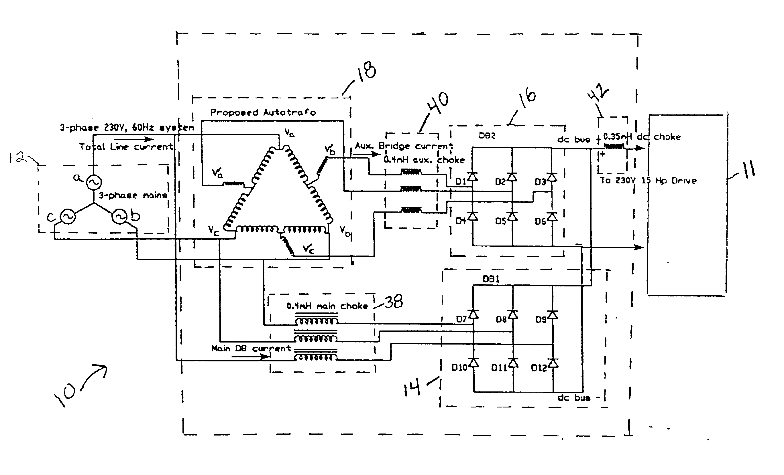
FIG. 4 shows an autotransformer-based 12 pulse rectification system 10 in accordance with the present invention. System 10 is operated by a three phase main power source 12 and is connected to a load 11 having a load power. The power source 12 has a main three phase voltage set consisting of va, vb, and vc wherein each main phase voltage has a main voltage amplitude and a main voltage phase.

System 10 includes a main rectifier mechanism 14, an auxiliary rectifier mechanism 16, and an autotransformer 18. For the purposes of discussion throughout this application, the...


PUM


Abstract

A system and method for reducing harmonics in a circuit is disclosed. The system comprises a main rectifier, (n3-1)auxiliary rectifiers connected to the main rectifier, and an autotransformer connected to both the main rectifier and the auxiliary rectifiers which provides 2n-pulse rectification where n equals the number of phases of the system. The autotransformer generates (n3-1)auxiliary voltage sets, each auxiliary voltage set having an auxiliary voltage amplitude, k, and an auxiliary voltage phase, α, wherein k=4+2⁢3⁢cos⁢(θ-7⁢π6)and wherein α=sin-1⁢(3⁢sin⁢ ⁢θ-0.5k)assuming a main voltage amplitude of one and a main voltage phase of ninety degrees, wherein θ=180⁢°nand its integral multiples for all possible real values of k. The main rectifier has a main rectifier power rating, Pmdb wherein Pmdb≥(n+32⁢n)times the load power, and the auxiliary rectifiers each have an auxiliary power rating, Pauxdb, wherein Pauxdb≤(32⁢n)times the load power.

Description

STATEMENT REGARDING FEDERALLY SPONSORED RESEARCH OR DEVELOPMENTNot Applicable.BACKGROUND OF THE INVENTIONThe present invention relates to a system and method for reducing harmonics in a circuit, and in particular, to an autotransformer-based system and method of current harmonics reduction in a circuit.AC to DC conversion is used in various applications such as motor drives. A three-phase diode bridge is a typical example of an AC to DC converter. These devices draw line currents that are rich in harmonics during the conversion process. With the widespread use of such non-linear devices to satisfy our technological needs, it has become necessary to tackle problems associated with current harmonics such as overheating of distribution transformers, transmission lines, voltage distortion and power system instability, all of which can lead to power system breakdowns. This has become all the more imperative due to the growing presence of loads that need good quality power such as compute...

Claims


Application Information

Patent Timeline
IPC IPC(8): H01F30/12H01F30/00H01F30/02H01F30/06
CPCH01F30/12H01F30/02
Inventor KAMATH, GIRISH RADHAKRISHNA
Owner BALDOR ELECTRIC COMPANY
Learn More