
Rapid coupling system

a coupling system and rapid technology, applied in the direction of couplings, pipe elements, water supply installations, etc., can solve the problems of stiff rapid coupling system, complicated structure of pressure relief valves included in the coupling elements, and dogged pressure relief valves

Inactive Publication Date: 2005-03-01
TEMA MARKETING
View PDF7 Cites 30 Cited by
  • Summary
  • Abstract
  • Description
  • Claims
  • Application Information

AI Technical Summary

Benefits of technology

The first coupling element to establish the rapid coupling is a plug element and the second coupling element is a socket element. The plug element and a journal are located together in a connecting block pertaining to the plug element. The socket element is arranged together with a control unit in another connecting block pertaining to the plug element. This ensures a very compact and functional establishment of the rapid coupling.
A preferred embodiment of the invention provides that the external control unit engages in the external pressure relief unit. The pressure relief unit is located in a third connecting block. The control unit comprises a displaceable control plunger with at least one cam. The control plunger with the cam engages in a pressure relief valve system which is arranged in the interior of the pressure relief unit. Depending on the position of the plug element in relation to the socket element, the pressure relief valve system can be opened and closed by means of the said cam. This provides a pressure relief unit that is characterised by a high operational reliability.

Problems solved by technology

A problem that occurs frequently with rapid coupling systems is that the pressure relief valves included in the coupling elements have a complicated structure.
In addition to this contamination of the media result in dogged pressure relief valves and stiff rapid coupling systems.
Another disadvantage is that depending on the type of rapid coupling system the plug element or the socket element or both coupling elements must be provided with the complicated pressure relief valves.

Method used


Image

  • Rapid coupling system
  • Rapid coupling system
  • Rapid coupling system

Examples


Embodiment Construction

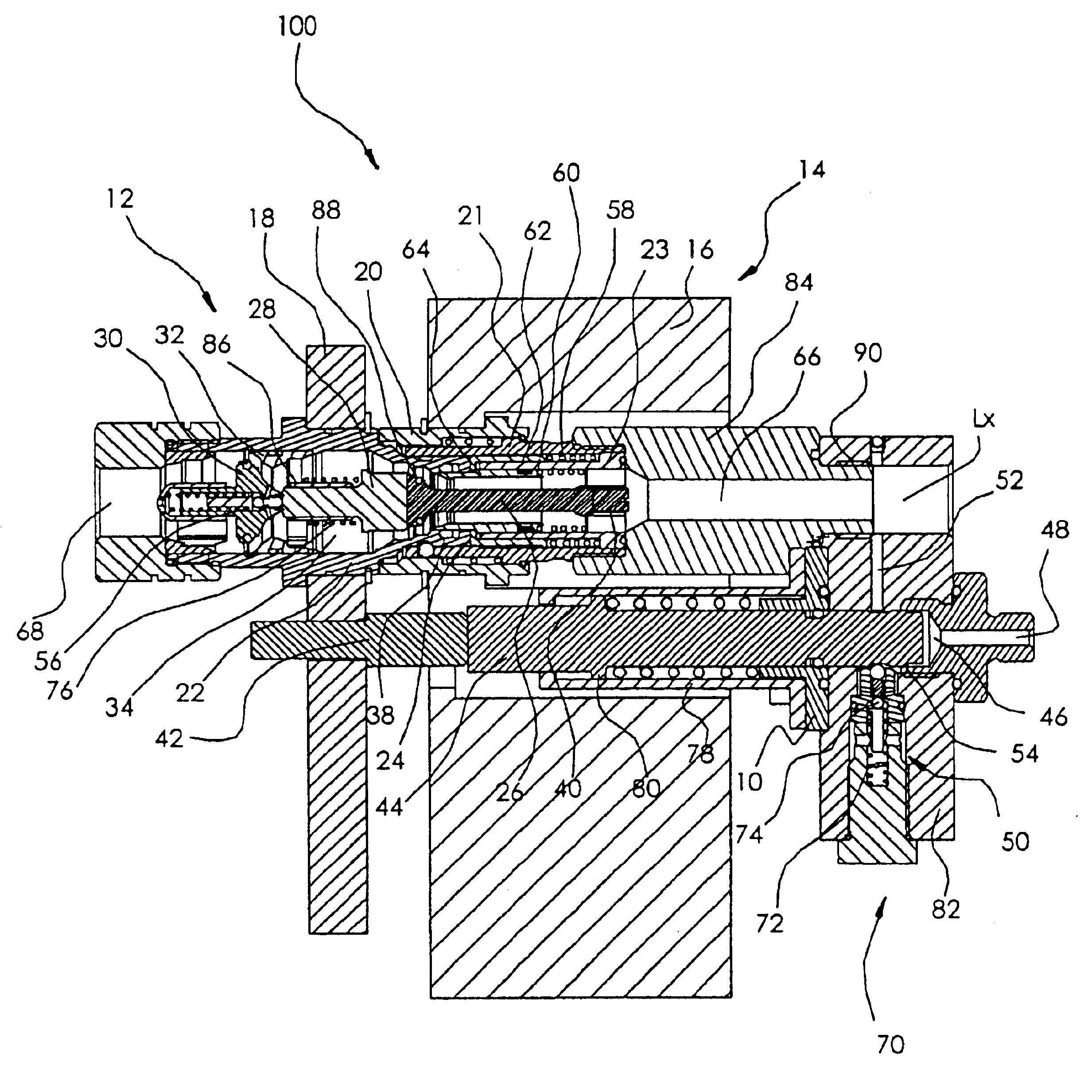
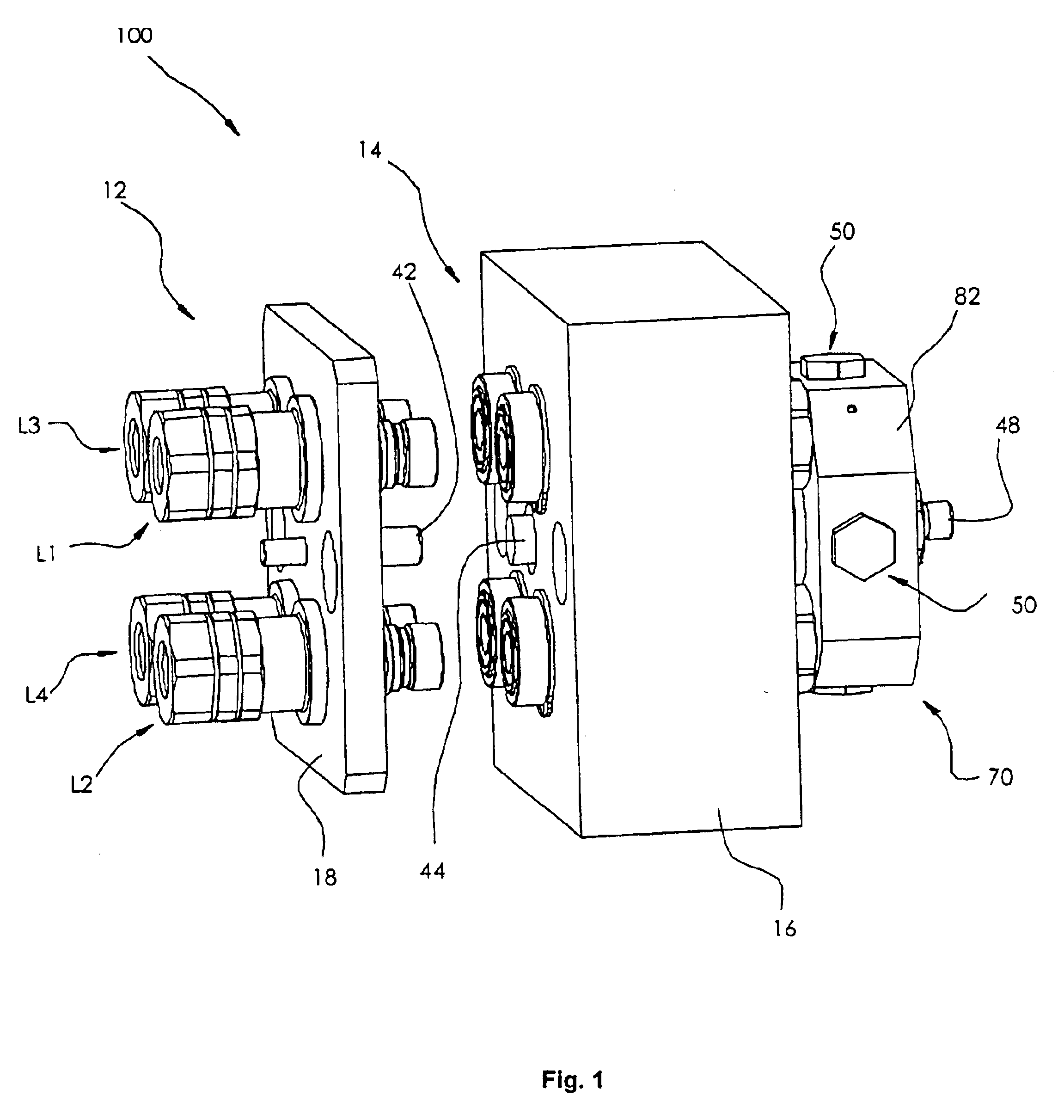
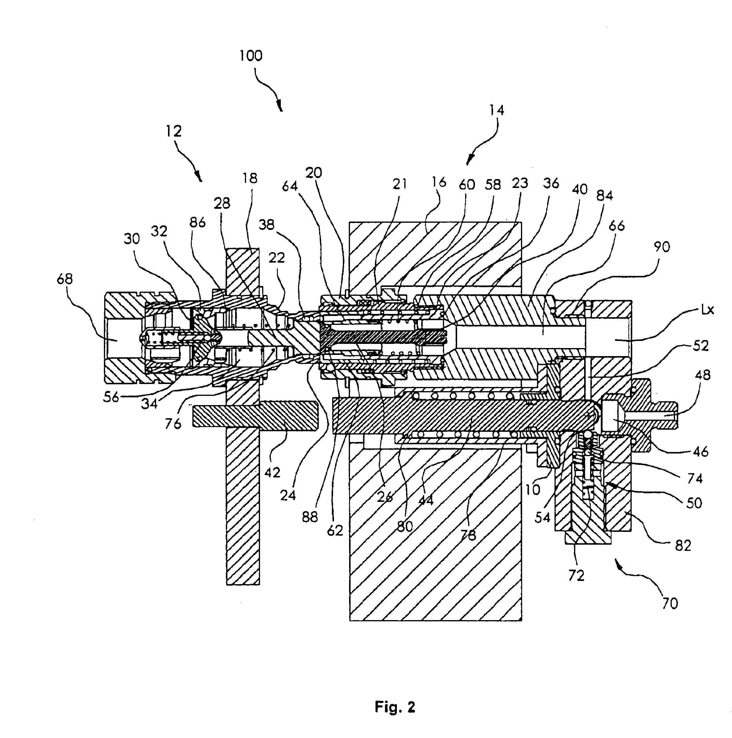
The rapid coupling system as a whole denoted by 100—depicted in FIG. 1 in an uncoupled state—provides a principally known basic construction. It consists of two coupling elements 12 and 14. Wherein the coupling element 12 is a plug element and the coupling element 14 is a socket element. The particularity of the rapid coupling system 100 is that several plug elements 12 of several pressurised lines L1, L2, L3, L4 to be connected with each other are arranged in a connecting block 18. The opposing socket elements 14 of the plug elements 12 are combined in one connecting block 16. The lines L1, L2, L3, L4 extending from the socket elements 14 are not depicted in FIG. 1.

FIG. 1 shows further a journal 42 that is centrically arranged in the connecting block 18 between the lines Lx. Opposing the said journal 42 there is a control plunger 44 between the socket elements 14 that is centrically arranged in the connecting block 16.

The socket elements 14 are furthermore connected with a pressure...


PUM


Abstract

A rapid coupling system for establishing a connection of at least two pressurized lines in a pressure sealed manner is provided. A first coupling plug element has an operating mechanism, including a journal, in a connecting block thereof. A second coupling socket element is adapted to be connected to the first coupling element in a pressure sealed manner. A control unit is arranged in a socket element connecting block and includes a displaceable plunger having at least one cam. A pressure relief unit is connectable to at least one of the pressure lines via a pressure relief connection. When the first and second coupling elements are connected to one another, the journal of the operating mechanism displaces the control plunger, causing at least one cam of the control plunger to engage the pressure relief unit.

Description

BACKGROUND OF THE INVENTIONThe invention relates to a rapid coupling system.Rapid coupling systems of the generic type are known. They serve for the connection of pressurised, medium-conducting lines and are used in the context of liquids, e.g. hydraulic oils, gasses and other appropriate media. Such rapid coupling systems comprise usually two coupling elements, wherein a first coupling element is a plug element and a second coupling element is a socket element. For coupling the plug element can be plugged into the socket element. The generic rapid coupling system serves also to connect lines which are under high media pressure. To this end the connection must be established either under pressure in the socket element and another time under pressure in the plug element of the coupling system. The connection can also be established under pressure in both coupling elements or in pressureless state of both coupling elements.In rapid coupling systems designed for high media pressure, e....

Claims


Application Information

Patent Timeline
IPC IPC(8): F16L37/30F16L37/28F16L37/00F16L37/56
CPCF16L37/30F16L37/56Y10S285/924Y10T137/87153Y10T137/87949Y10T137/87161
Inventor KNUTHSON, PER
Owner TEMA MARKETING
Learn More