Eureka AIR delivers breakthrough ideas for toughest innovation challenges, trusted by R&D personnel around the world.

Flexible fluid containment vessel

a technology for fluid containment vessels and containers, applied in special-purpose vessels, vessel construction, transportation and packaging, etc., can solve the problems of not only the cost involved in using such a transport vehicle, but also the added expense of its return trip, unloading, and unloading, etc., and achieve the effect of preventing the deterioration of the container

Inactive Publication Date: 2005-03-01
ALBANY INT CORP
View PDF110 Cites 32 Cited by
  • Summary
  • Abstract
  • Description
  • Claims
  • Application Information

AI Technical Summary

Benefits of technology

A further object of the invention is to provide for a means for reinforcing of such an FFCV so as to effectively distribute the load thereon and inhibit rupture.
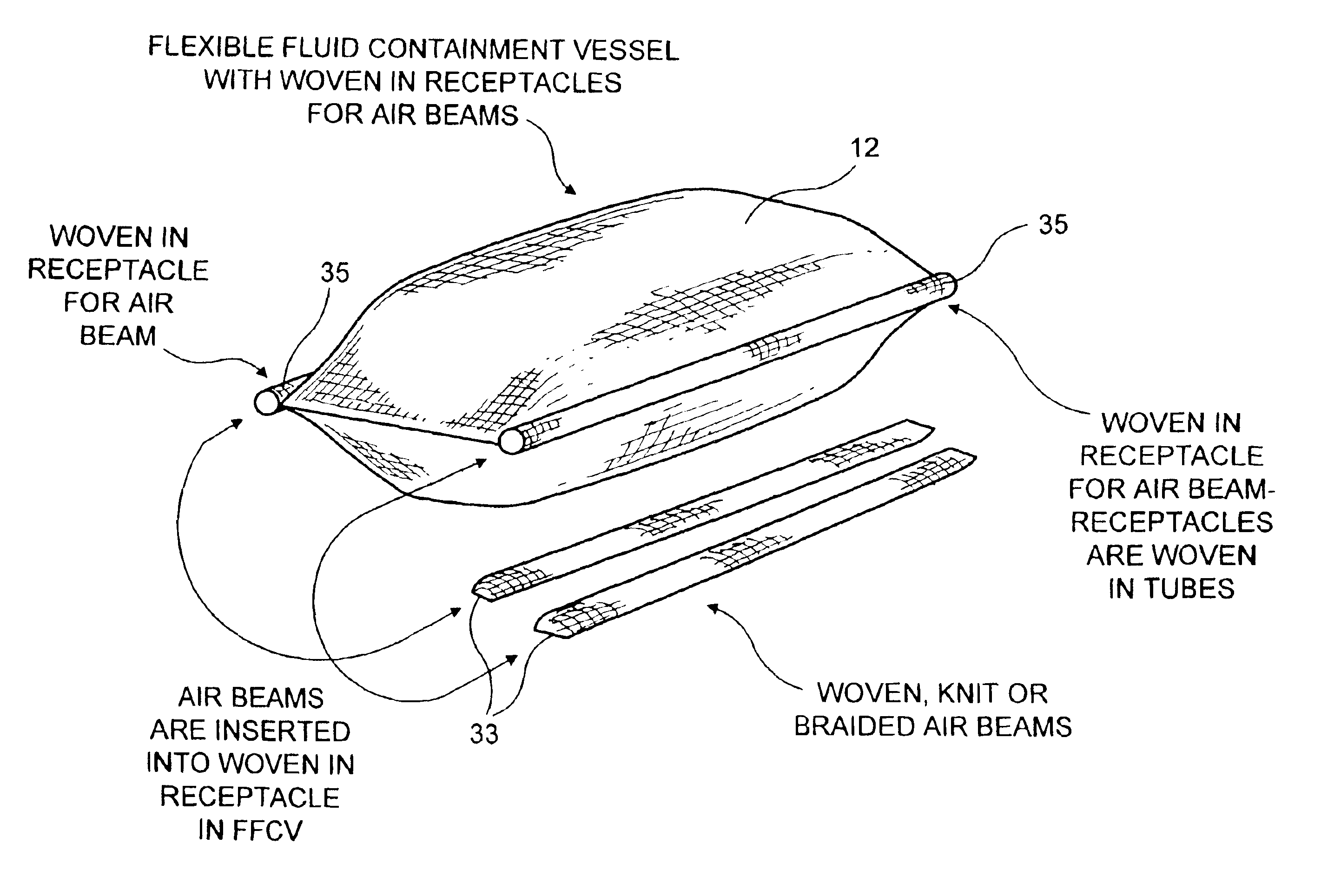
The beams also provide buoyancy to the FFCV as the cargo is unloaded to keep it afloat, since the empty FFCV would normally be heavier than salt water. Valves may be provided which allow pressurization and depressurization as the FFCV is wound up for storage.
In the situation where more than one FFCV is being towed, it is envisioned that one way is that they be towed side by side. To increase stability and avoid “roll over”, a plurality of beam separators, preferably containing pressurized air or other medium, would be used to couple adjacent FFCVs together along their length. The beam separators can be affixed to the side walls of the FFCV by way of pin seam connectors or any other means suitable for purpose.
In addition, the present invention includes fiber reinforcements woven into the tube used to construct the FFCV. These reinforcement fibers can be spaced in the longitudinal direction about the circumference of the tube and in the vertical direction along the length of the tube. In addition to providing reinforcement, such an arrangement may allow for the use of a lighter weight fabric in the construction of the tube. Since they are woven into the fabric, external means for affixing them are not necessary nor do they create additional drag during towing.
The present invention also discloses methods rendering the tube impervious. In this regard various methods are proposed so as to allow for conventional coating to be used, i.e. spray, dip coating, etc. The tube can be coated on the inside, outside, or both with an impervious material. The tube, if the weave is tight enough, may be inflated with the outside spray coated. A non-stick bladder may be inserted, if necessary, to allow the coating of the outside. The bladder is then removed and the tube can be inflated and the inside coated. Alternatively, a flat non-stick liner can be inserted into the tube to prevent the sticking of the interior surface during coating and thereafter it is removed. Also, mechanical means may be inserted within the tube during coating to keep the interior surfaces apart during coating.

Problems solved by technology

Obviously, this involves, not only the cost involved in using such a transport vehicle, but the added expense of its return trip, unloaded, to pick up fresh cargo.
However, technical problems with regard to such containers persist even though developments over the years have occurred.
It does not teach, however, how this would be accomplished with a tube of such magnitude.
Seams are known to be a source of bag failure when the bag is repeatedly subjected to high loads.
Other problems face the use of large transport containers.
In this regard, when partially or completely filled flexible barges or transport containers are towed through salt water, problems as to instability are known to occur.
This instability is described as a flexural oscillation of the container and is directly related to the flexibility of the partially or completely filled transport container.
Long flexible containers having tapered ends and a relatively constant circumference over most of their length are known for problems with snaking.
However, such containers have size limitations due to the magnitude of the forces placed thereon.
While high towing speeds are attractive in terms of minimizing the towing time, high towing speeds result in high towing forces and high fuel consumption.
This, however, results in an increase in the container weight and a decrease in the flexibility of the material.
This, in turn, results in an increase in the difficulty in handling the flexible transport container, as the container is less flexible for winding and heavier to carry.
Moreover, fuel consumption rises rapidly with increased towing speed.
For a particular container, there is a combination of towing speed and fuel consumption that leads to a minimum cost for transportation of the cargo.
Moreover, high towing speeds can also exacerbate problems with snaking.
However, further increases in the capacity of elongated hexagon shaped containers will result in lower towing speeds and increased fuel consumption.
However, in towing flexible containers side by side, lateral forces caused by ocean wave motion creates instability which results in one container pushing into the other and rolling end over end.
Such movements have a damaging effect on the containers and also effect the speed of travel.
Another problem with such flexible containers is the large towing forces thereon, in addition to the forces created by extreme sea and wind conditions.
Such reinforcements, however, suffer the disadvantages of requiring their attachment to the container while also being cumbersome, especially if the container is intended to be wound up when emptied.
Moreover, external reinforcements on the container's surface provide for increased drag during towing.
Furthermore, while as aforenoted, a seamless flexible container is desirable and has been mentioned in the prior art, the means for manufacturing such a structure has its difficulties.
It is economically impractical to build a roll system to coat a fabric of the large size envisioned.
However, with an extremely large flexible woven seamless container, in order of 40′ diameter and 1000′ in length or larger, conventional coating methods would be difficult.
While relatively small flat fabrics are readily coated, a tubular unitary structure, extremely long and wide, is much more difficult.

Method used


Image

  • Flexible fluid containment vessel
  • Flexible fluid containment vessel
  • Flexible fluid containment vessel

Examples


Embodiment Construction

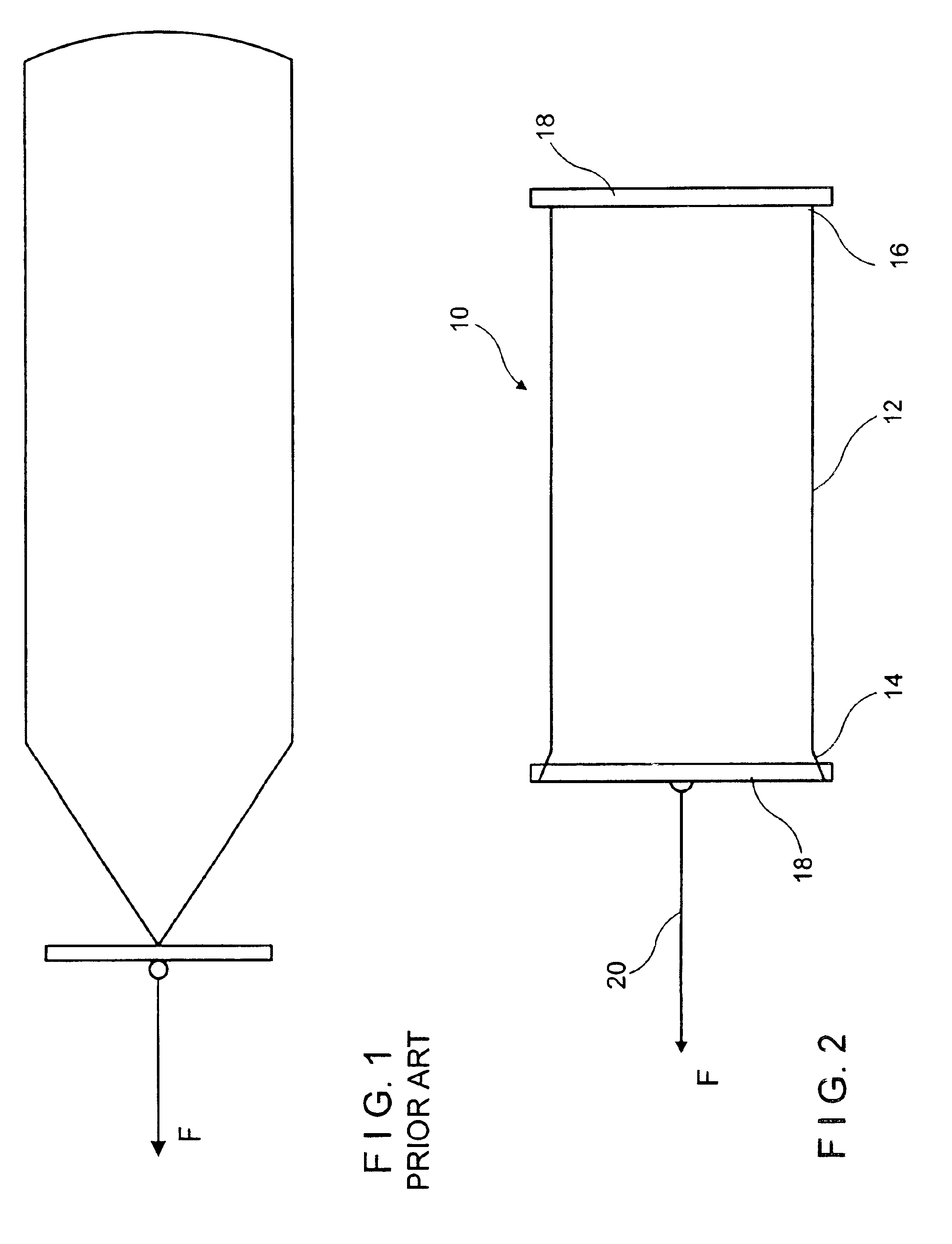
The proposed FFCV 10 is intended to be constructed of a seamless woven impermeable textile tube. The tube's configuration may vary. For example, as shown in FIG. 2, it would comprise a tube 12 having a substantially uniform diameter (perimeter) and sealed on each end 14 and 16. It can also have a non-uniform diameter or non-uniform shape. See FIG. 5. The respective ends 14 and 16 may be closed, pinched, and sealed in any number of ways, as will be discussed. The resulting coated structure will also be flexible enough to be folded or wound up for transportation and storage.

Before discussing more particularly the FFCV design of the present invention, it is important to take into consideration certain design factors. The even distribution of the towing load is crucial to the life and performance of the FFCV. During the towing process there are two types of drag forces operating on the FFCV, viscous drag and form drag forces. The total force, the towing load, is the sum of the viscous a...


PUM

PropertyMeasurementUnit
Lengthaaaaaaaaaa
Structureaaaaaaaaaa
Sizeaaaaaaaaaa

Abstract

A seamless, woven, flexible fluid containment vessel or vessels for transporting and containing a large volume of fluid, particularly fresh water, having beam stabilizers, beam separators, reinforcing, and the method of making the same.

Description

FIELD OF THE INVENTIONThe present invention relates to a flexible fluid containment vessel (sometimes hereinafter referred to as “FFCV”) for transporting and containing a large volume of fluid, particularly fluid having a density less than that of salt water, more particularly, fresh water, and the method of making the same.BACKGROUND OF THE INVENTIONThe use of flexible containers for the containment and transportation of cargo, particularly fluid or liquid cargo, is well known. It is well known to use containers to transport fluids in water, particularly, salt water.If the cargo is fluid or a fluidized solid that has a density less than salt water, there is no need to use rigid bulk barges, tankers or containment vessels. Rather, flexible containment vessels may be used and towed or pushed from one location to another. Such flexible vessels have obvious advantages over rigid vessels. Moreover, flexible vessels, if constructed appropriately, allow themselves to be rolled up or folde...

Claims


Application Information

Patent Timeline
IPC IPC(8): B63B35/28B65D88/78B65D88/16B65D88/00B63B35/00D06N7/00D06N3/00B63B7/08B63B1/00B63B25/08B63B38/00
CPCB63B35/285B65D88/16D06N3/0056B65D88/78D06N2209/128B63B35/44
Inventor EAGLES, DANATONEY, CRAYTON GREGORYTUPIL, SRINATHLAWTON, DONALD TRIPPDONOVAN, JAMES G.DUTT, WILLIAMROMANSKI, ERICRYDIN, BJORNREXFELT, JAN
Owner ALBANY INT CORP
Why Eureka
Eureka Blog
Learn More