
Mower

a rotary mower and cutter head technology, applied in the field of implements, can solve the problems of lack of adapt inability to adjust, adaptability and control, and inability to mow on the opposite side of the row of plants, so as to achieve efficient mow different surface contours and efficient mow.

Inactive Publication Date: 2005-03-01
SCORDILIS FR P
View PDF18 Cites 36 Cited by
  • Summary
  • Abstract
  • Description
  • Claims
  • Application Information

AI Technical Summary

Benefits of technology

"The invention is a dual cutter head mower that can be attached to a wheeled support vehicle such as a tractor. The mower has a support frame that can be adjusted to allow the cutter heads to be moved laterally while mowing. The cutter heads can be tilted to match the slope of the ground and can be pivoted to a transport position. The mower can also be reversed to mow on the other side of the vehicle. The cutter heads can be adjusted to overlap with each other or mow on the sides of fences or trees. The mower attachment can be reversed and the cutter heads can be repositioned when the attachment is reversed. The mower also has a liquid spray apparatus for applying herbicide, fertilizer, or insecticide to the ground area."

Problems solved by technology

However, the performance of this previously marketed mowing machine has not been found to be entirely satisfactory in its adjustability, adaptability and controls to provide safe and satisfactory performance and lacks adaptability to mow on opposite sides of rows of plants such as found in nurseries and the like.

Method used


Image

  • Mower
  • Mower
  • Mower

Examples


first embodiment

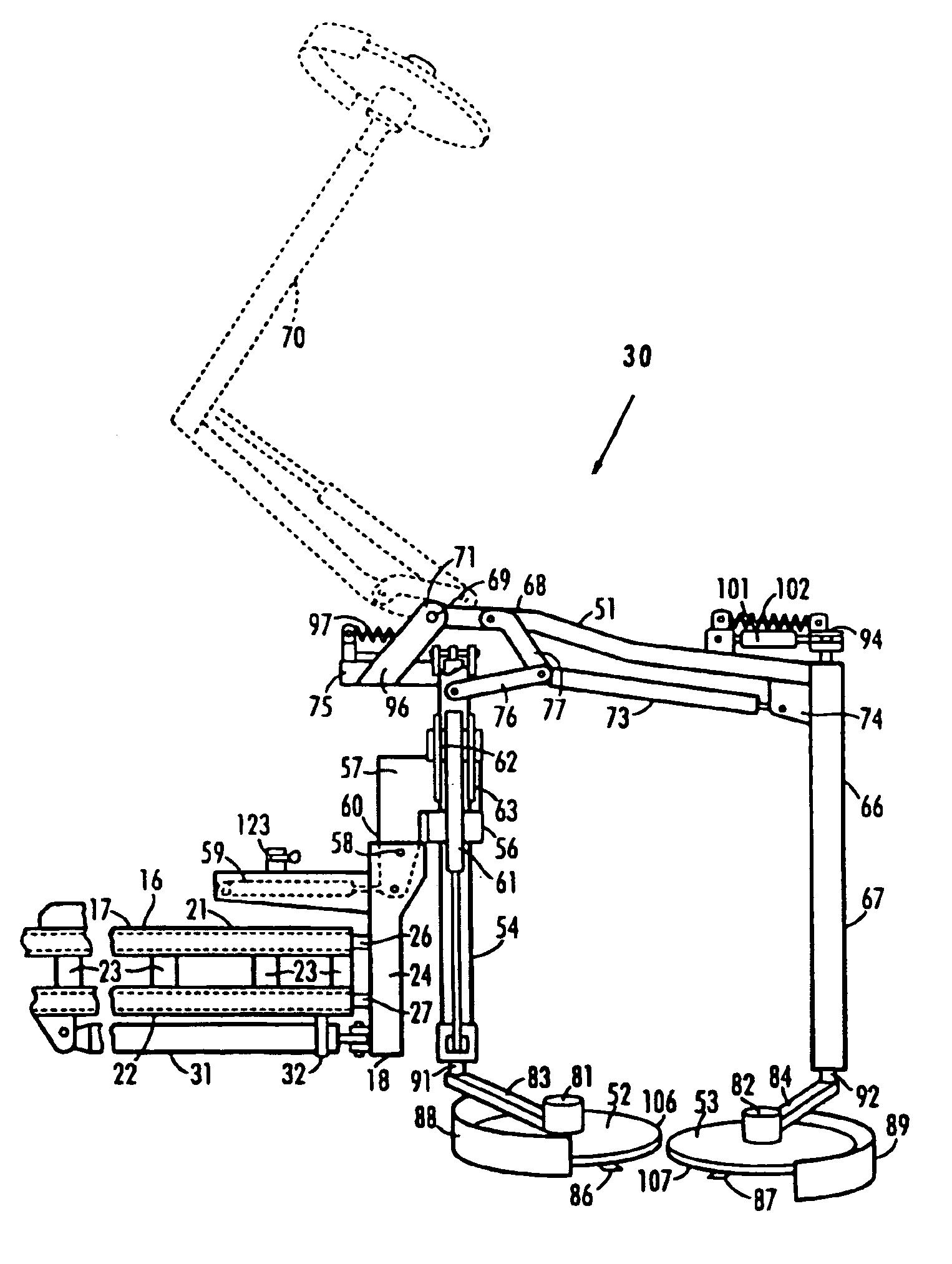
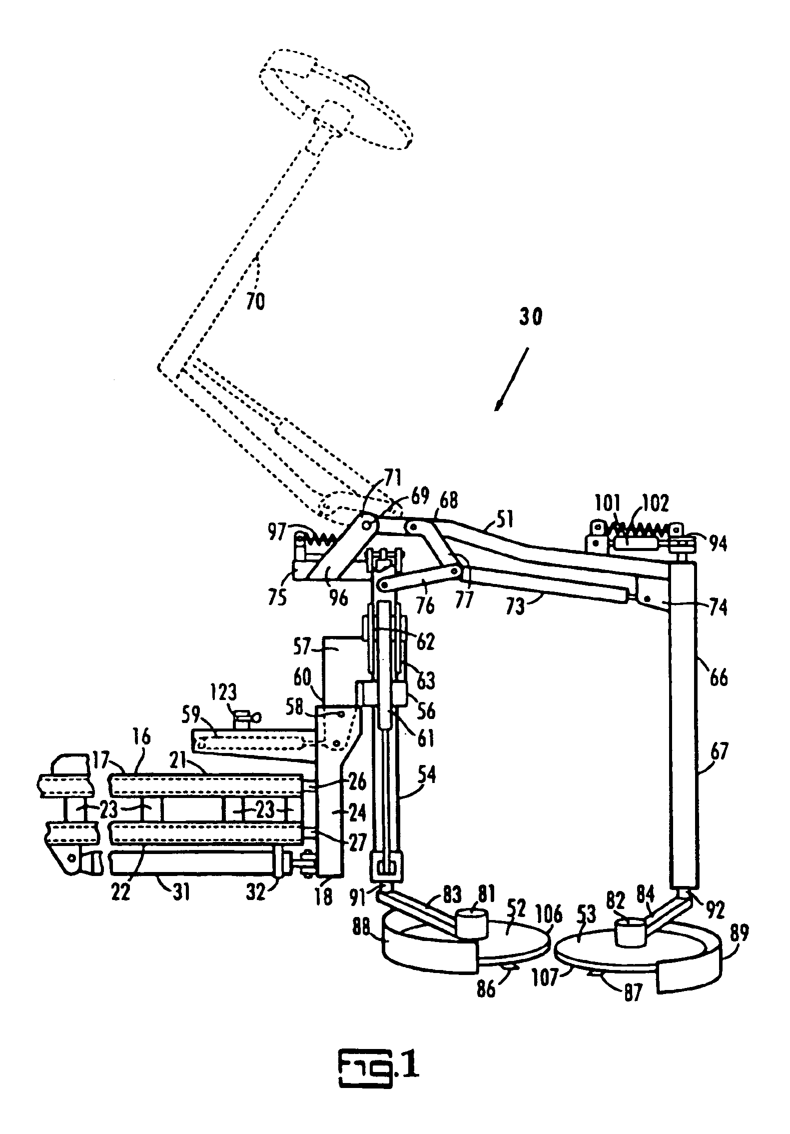
FIG. 1 is a rear view of a dual cutter head mower 30 with some components removed and some parts broken away for illustration purposes. A mower support structure or mainframe 16 includes a first subframe 17 and a second subframe 18. The first subframe 17 includes a pair of guide members in a form of parallel square section hollow tubes 21, 22 to which cross braces 23 are welded. The second subframe 18 includes a pair of parallel guide members 26, 27 having a sliding fit in the hollow tubes 21, 22 of the first subframe 17 and having a post 24 to which the slide members 26, 27 are rigidly secured as by welding. A double acting linear actuator in the form of a double acting hydraulic ram 31 is interconnected between said subframes 17, 18 and is operable to adjust the lateral position of the second subframe 18 as much as 40 inches. A U shaped support strap 32 welded to the tube 22 supports the cylinder component of the hydraulic ram 31.

As shown in FIG. 8, the first subframe 17 is adapte...

second embodiment

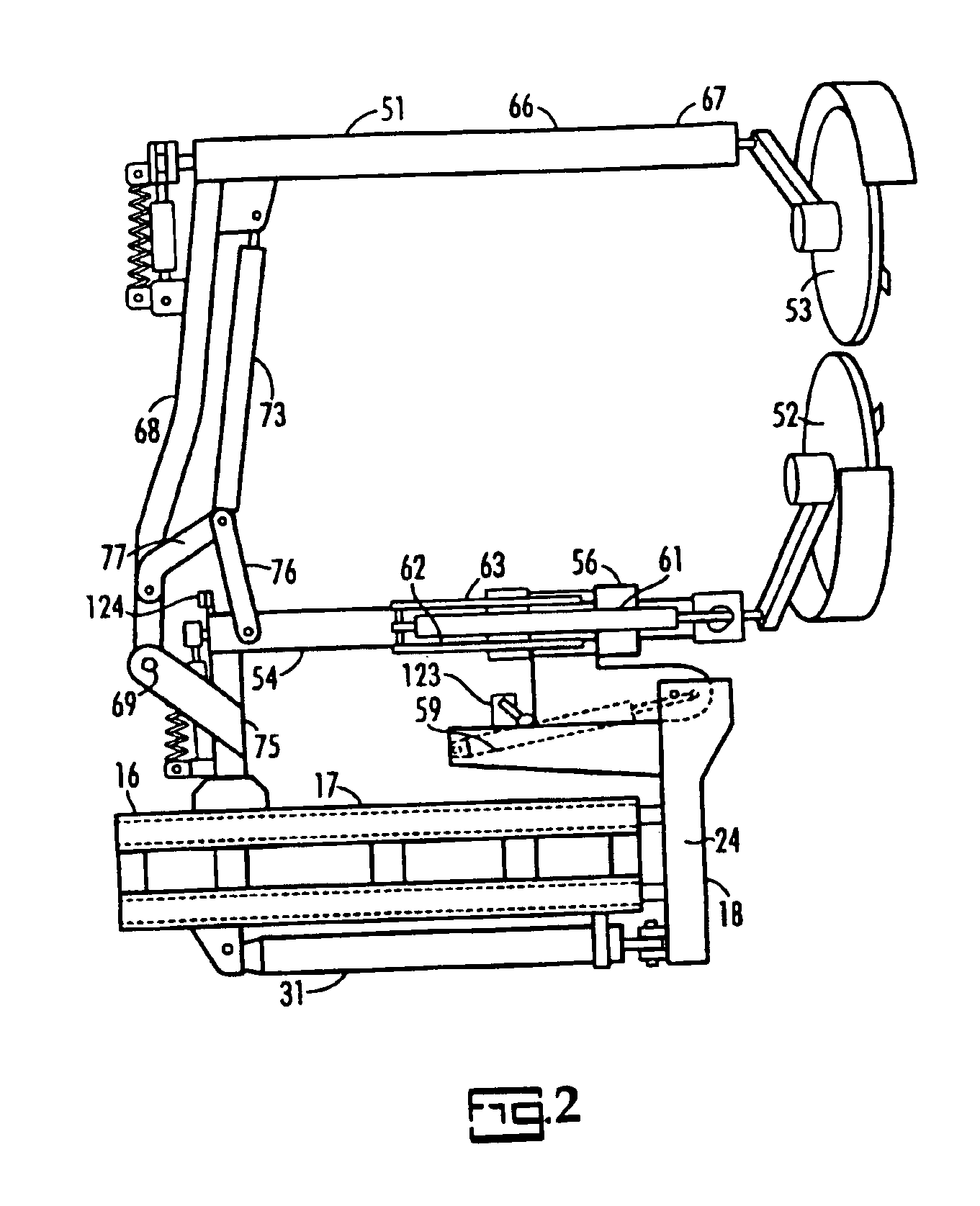
The mower 200 of the invention illustrated in FIGS. 11-29 has a support frame 201 which includes a first subframe 202 having upper and lower parallel guide members in the form of square section tubes 203, 204 to which six cross braces are welded. Upper and lower three point hitch connections or components 211, 212, 213, 214, 216, 217 are welded to the first subframe 202 which permit a three point hitch equipped tractor 218 to be hitched to either of the front and rear sides of the support frame 201. A gear box 221 mounted on support frame has a fore and aft extending input shaft 222 with opposite ends extending from its front and rear sides, respectively.

A second subframe 226 includes a pair of parallel guide members 227, 228 having a sliding fit in the hollow tubes 203, 204 of the first subframe 202 and having a vertically extending post 229 welded to their ends extending from the tubs 203, 204. A double acting linear actuator in the form of a double acting hydraulic ram 231 has it...


PUM


Abstract

A dual cutter head, self contained mower (30, 200) is provided for cutting vegetation beneath and on opposite sides of guard rails or cable barriers, and on opposite sides of rows of small trees, hedges, walls or fences. The cutter heads (52, 53 and 252, 253) are staggered to cut overlapping swathes and are adjustably biased to permit the cutter heads to move laterally away from one another when an obstacle is encountered. The outer cutter head (53, 253) can be swung to an overhead position to avoid road signs, poles or the like. The mower can be front or rear mounted and can be reversed to cut at either side of the supporting vehicle. A spray system (323) applies herbicides or other liquids to the area being mowed.

Description

TECHNICAL FIELDThis invention relates to implements in the form of power driven mowers and more particularly to a double cutter head rotary mower for cutting vegetation and light brush under and on opposite sides of guardrails, media safety cables, fences and for mowing on opposite sides of rows of plants in nurseries, vineyards and tree farms.BACKGROUND OF THE INVENTIONWhen conventional mowers are used to mow the highway areas where guardrails or media safety cables are present, a strip of uncut vegetation is left beneath the guardrail or safety cable. In an attempt to remedy this problem a double cutter head mower has been marketed which places cutter heads on opposite sides of the guardrail or cable barrier. However, the performance of this previously marketed mowing machine has not been found to be entirely satisfactory in its adjustability, adaptability and controls to provide safe and satisfactory performance and lacks adaptability to mow on opposite sides of rows of plants su...

Claims


Application Information

Patent Timeline
Patent Type & Authority Patents(United States)
IPC IPC(8): A01D34/00A01D34/86
CPCA01D34/863
Inventor SCORDILIS, FRANK P.
Owner SCORDILIS FR P
Learn More