
Spark plug having an oil film on an intermediate portion of the insulator or intermediate portion of the metallic shell

Inactive Publication Date: 2005-02-22
NGK SPARK PLUG CO LTD
View PDF6 Cites 24 Cited by
  • Summary
  • Abstract
  • Description
  • Claims
  • Application Information

AI Technical Summary

Benefits of technology

An object of the present invention is to solve the above conventional problems or to prevent dielectric breakdown which may otherwise occur on an insulator, particularly on an intermediate body portion of the insulator that constitutes a spark plug for an internal combustion engine.
Since an embodiment of the present invention has the above structure, even when the surface of the intermediate body portion of the insulator has a dent or protrusion, or even when, during assembly of the metallic shell, a fine defect such as crack is formed on the surface of the intermediate body portion of the insulator, the above oil film present between the insulator and an ambient air layer has an effect of easing a great change in dielectric constant between the surface of the insulator and the ambient air layer. Further, the oil film formed of liquid oil smoothes a dent, protrusion or a fine defect such as a crack present on the surface of the insulator. As a result, even when high voltage is applied for spark discharge, electric field concentration is less likely to occur, thereby preventing dielectric breakdown.

Problems solved by technology

Further, a dent, protrusion or a fine defect such as a crack can be formed on the surface of the insulator, particularly on the surface of the intermediate body portion of the insulator closely facing the intermediate hole portion of the metallic shell, during sintering of the insulator or during assembly of the metallic shell and the insulator.
Upon the above application of high voltage, electric field concentration is apt to occur at the above dent or protrusion or like defect present on the surface of the insulator due to a great change in dielectric constant between the surface of the insulator and an ambient air layer, potentially resulting in dielectric breakdown and thus misfire at the time of spark discharge.

Method used


Image

  • Spark plug having an oil film on an intermediate portion of the insulator or intermediate portion of the metallic shell
  • Spark plug having an oil film on an intermediate portion of the insulator or intermediate portion of the metallic shell
  • Spark plug having an oil film on an intermediate portion of the insulator or intermediate portion of the metallic shell

Examples


Embodiment Construction

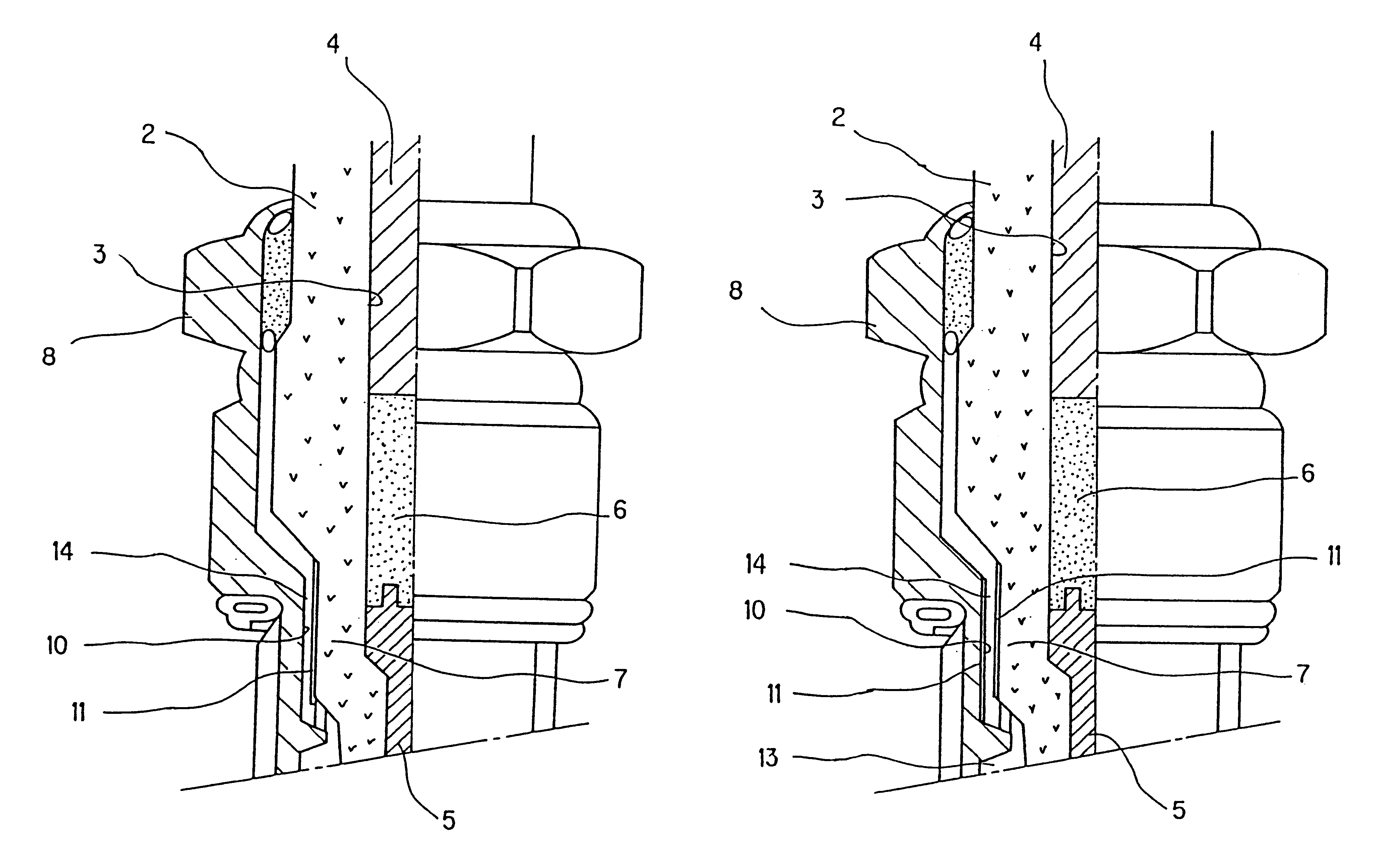
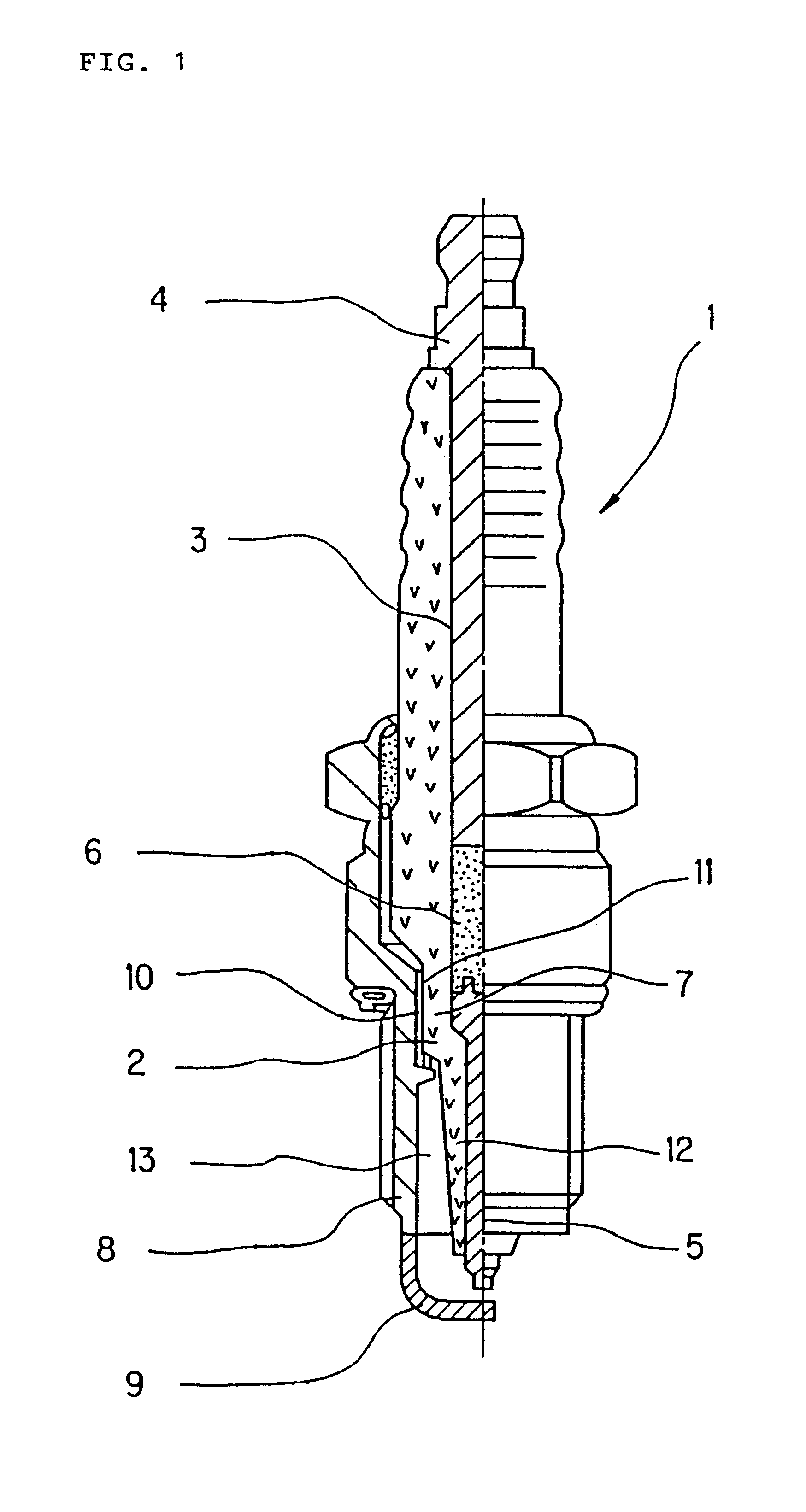
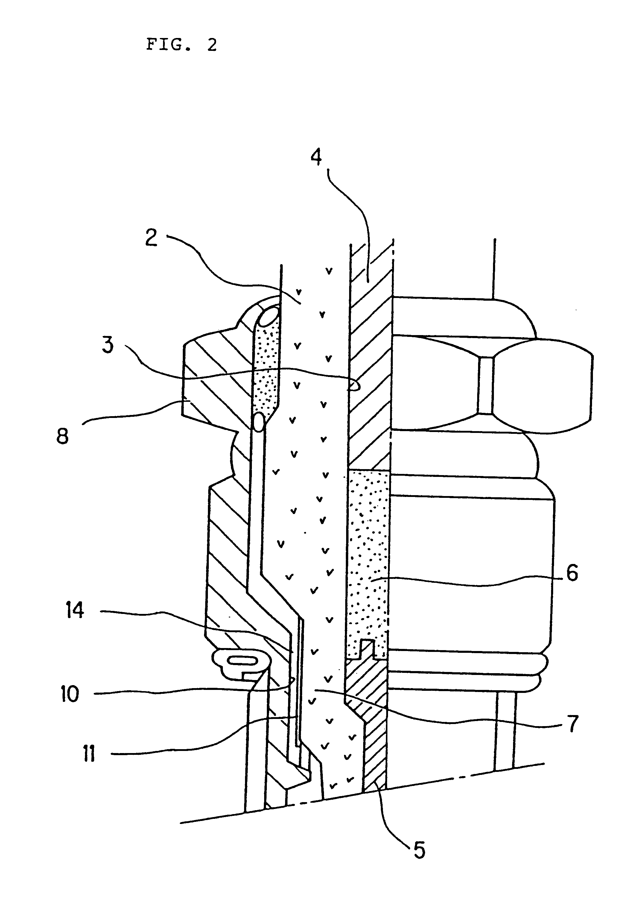
Referring now to FIGS. 1, 2 and 3, numeral 1 denotes a spark plug for an internal combustion engine according to a first embodiment of the present invention. In the spark plug 1 for an internal combustion engine, an insulator 2 has an axial bore 3. A terminal electrode 4 is held at a rear end portion of the axial bore 3. Also, a center electrode 5 is held in the axial bore 3 such that the tip end of the center electrode 5 projects from the insulator 2 and the other end of the center electrode 5 is sealed with a conductive glass seal 6. A metallic shell 8 integrally secures an intermediate body portion 7 of the insulator 2 which holds the center electrode 5 whose tip projects therefrom. A ground electrode 9 is integrated with the metallic shell 8 in such a manner as to face the tip of the center electrode 5.

In the above spark plug 1 for an internal combustion engine, an oil film 11 of, for example, engine oil, rust preventative oil, electrical insulating oil, industrial lubrication o...


PUM


Abstract

In a spark plug for an internal combustion engine oil is applied onto at least either the surface of an intermediate body portion of an insulator or the surface of an intermediate hole portion of a metallic shell, thereby forming an oil film. Since the oil film has a dielectric constant falling between those of the insulator and an ambient air layer, a great change in dielectric constant between the insulator and the ambient air layer is eased. Also, since the oil film is of liquid, the oil film smoothes a dent or protrusion or a fine defect such as crack present on the surface of the intermediate body portion of the insulator. Thus, electric field concentration is suppressed, thereby preventing dielectric breakdown caused by such a dent, protrusion or fine defect.

Description

BACKGROUND OF THE INVENTION1. Field of the InventionThe present invention relates to a structure of and a method for manufacturing a spark plug for an internal combustion engine.2. Description of the Related ArtConventionally, in a spark plug used in an internal combustion engine, in order to prevent occurrence of dielectric breakdown on the surface of the insulator, a center electrode whose tip projects from the insulator is held in an axial bore formed in the insulator such that the other end of the center electrode is glass-sealed, and, by means of packing, a portion of the surface of the insulator corresponding to the glass-sealed portion of the center electrode is isolated from the high-temperature, high-pressure working atmosphere of the spark plug.However, the insulator which constitutes the spark plug, particularly an intermediate body portion of the insulator united with a metallic shell, is always subjected to radial pressure applied from the inside by the glass seal that ...

Claims


Application Information

Patent Timeline
IPC IPC(8): H01T13/36H01T13/20H01T21/02
CPCH01T13/36
Inventor MATSUTANI, WATARU
Owner NGK SPARK PLUG CO LTD
Learn More