
Tension mask assembly for use in vacuum deposition of thin film of organic electroluminescent device

Inactive Publication Date: 2005-02-22
SAMSUNG DISPLAY CO LTD
View PDF15 Cites 77 Cited by
  • Summary
  • Abstract
  • Description
  • Claims
  • Application Information

AI Technical Summary

Benefits of technology

Accordingly, it is an object of the present invention to provide a mask frame assembly used in vacuum deposition of thin films of an organic electroluminescent (EL) device, in which variations in pattern width as a result of an increase in mask size can be reduced, the total pitch of unit masks can be easily adjusted, and additional variations in total pitch due to external or internal stress of the mask and frame can be minimized.
It is another object of the present invention to provide a mask frame assembly used in vacuum deposition of thin films of an organic EL device, which is constructed of a number of unit masks, so that the size of the mask can be increased without adverse effects.
It is still another object of the present invention to provide a mask frame assembly used in vacuum deposition of thin films of an organic EL device, in which the pitch of strips in a traverse direction of unit masks can be finely adjusted, thereby solving problems associated with total pitch variations of the mask.

Problems solved by technology

However, when this photolithography method is applied to etch the second electrodes, liquid permeates into the interface between the organic emissive layer and the second electrodes while the resist used is stripped off and the second electrodes are etched, thereby degrading the performance and lifetime characteristics of the organic EL device.
This problem becomes serious as the size of the substrate increases.
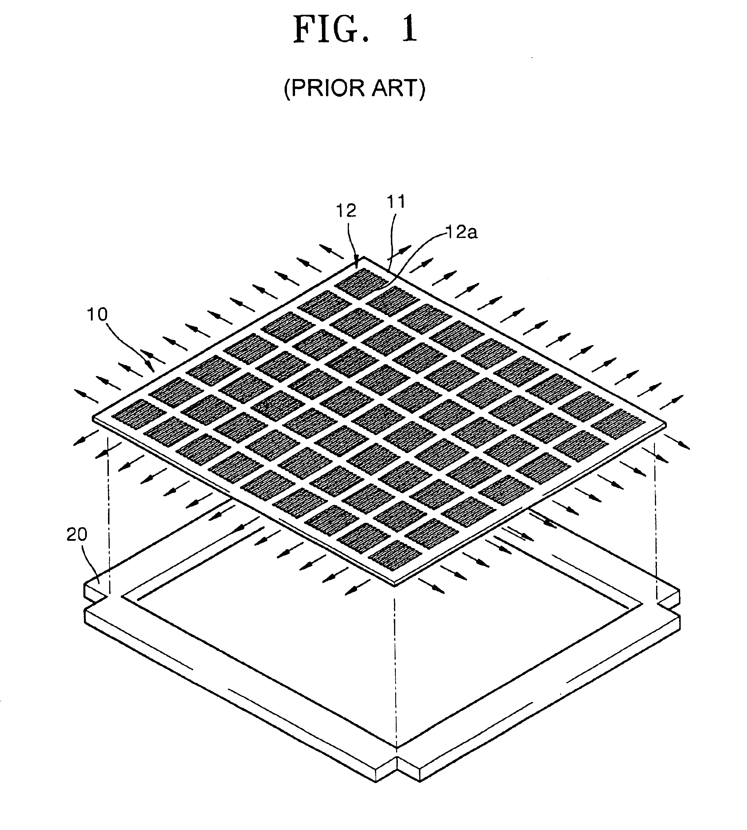
This conventional mask 10 has a relatively large size for large scale production, so the problem of sagging by its own weight becomes serious even when uniform tension is applied to each side of the mask to fix it to the rectangular frame 20.
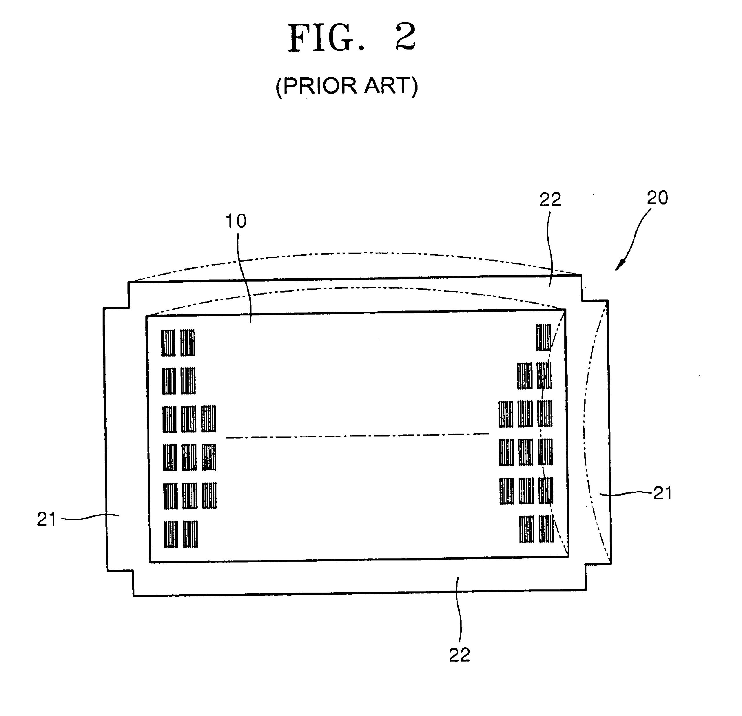
Although uniform tension is applied to weld the mask 10 to the frame, the distortion of the mask and displacement of the unit electrode patterns formed on a substrate to the mask patterns make total pitch adjustment difficult.
Although the conventional masks described above are supported by the frame and are formed of a magnetic material to give a magnetic affinity for a target substrate, the inherent problems, such as variations in strip pitch due to the weight and the tensile strain of the mask, damage of the organic layer in moving and handling the mask due to increased attraction to the glass substrate, and total pitch variations due to internal stress of the mask and frame occur.

Method used


Image

  • Tension mask assembly for use in vacuum deposition of thin film of organic electroluminescent device
  • Tension mask assembly for use in vacuum deposition of thin film of organic electroluminescent device
  • Tension mask assembly for use in vacuum deposition of thin film of organic electroluminescent device

Examples


Embodiment Construction

Reference will now be made in detail to the embodiments of the present invention, examples of which are illustrated in the accompanying drawings, wherein like reference numerals refer to like elements throughout.

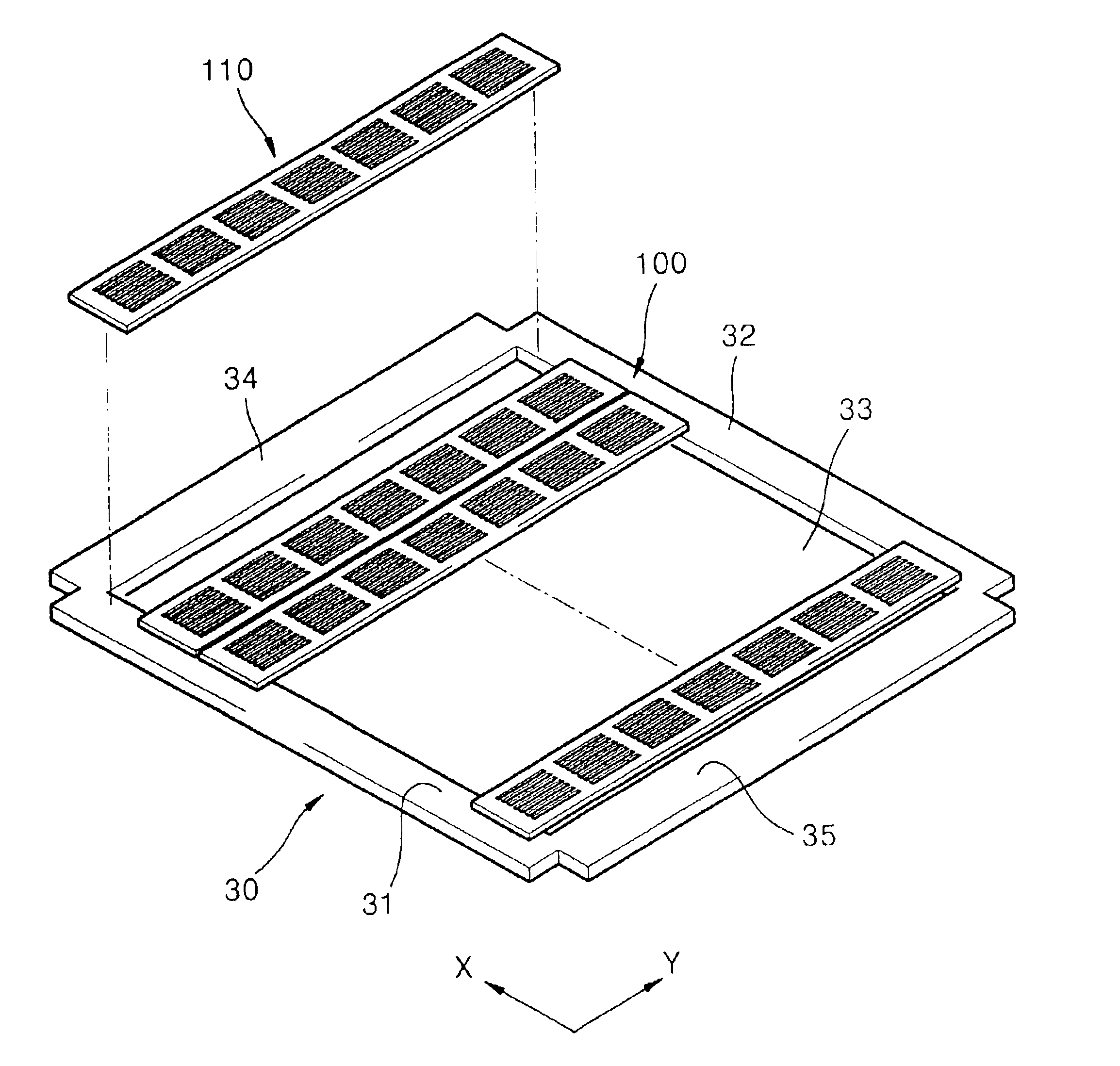
An embodiment of a mask frame assembly used in vacuum deposition of thin films of an organic electroluminescent (EL) device according to the present invention is illustrated in FIG. 4. Referring to FIG. 4, the mask frame assembly includes a frame 30 and a mask 100 whose two edges are supported under tension by the frame 30.

The frame 30 includes support members 31 and 32, which are arranged parallel to each other, and elastic members 34 and 35 connected to the edges of the support members 31 and 32 to define a rectangular opening 33. The frame 30 should be rigid enough to apply tension to a unit mask 110 described infra. Any structure can be applied to the frame 30 as long as it does not cause interference between a target substrate and the mask 100.

The mask 100 includes a nu...


PUM

PropertyMeasurementUnit
Lengthaaaaaaaaaa
Lengthaaaaaaaaaa
Elasticityaaaaaaaaaa

Abstract

A mask frame assembly used in vacuum deposition of thin films of an organic electroluminescent device. The mask frame assembly includes a frame having an opening and at least two unit masks which each have at least one unit masking pattern portion in the direction of the unit mask and two edges which are fixed to the frame under tension.

Description

CROSS-REFERENCE TO RELATED APPLICATIONSThis application claims the benefit of Korean Application No. 2001-76490, filed Dec. 5, 2001, in the Korean Industrial Property Office, the disclosure of which is incorporated herein by reference.BACKGROUND OF THE INVENTION1. Field of the InventionThe present invention relates to a metal mask, and more particularly, to a mask frame assembly used in deposition of thin films of an organic electroluminescent device.2. Description of the Related ArtRecently, electroluminescent (EL) devices regarded as self-luminous type display devices have been receiving a lot of attention as a next-generation display device due to the advantages of a wide viewing angle and good contrast and rapid response characteristics.EL devices are classified into inorganic EL devices and organic EL devices depending upon the material of an emissive layer. Organic EL devices can realize color display and have better luminance and response characteristics than inorganic EL dev...

Claims


Application Information

Patent Timeline
IPC IPC(8): C23C14/04H01L51/56H01L51/50H01L51/40H01L51/05H05B33/10C23C14/12C23C14/24H01L51/00
CPCC23C14/042H01L51/56H01L51/001H10K71/164H10K71/00H10K71/166H05B33/10
Inventor KANG, CHANG HO
Owner SAMSUNG DISPLAY CO LTD
Learn More