
BOP assembly with metal inserts

a metal insert and bop technology, applied in the direction of sealing/packing, cable terminations, borehole/well accessories, etc., can solve the problems of limited acceptance, metal inserts have difficulty in reliably sealing against a high pressure differential across the closed bop, etc., and achieve the effect of low diameter and high reliability of the bop

Inactive Publication Date: 2005-02-22
VARCO SHAFFER
View PDF6 Cites 51 Cited by
  • Summary
  • Abstract
  • Description
  • Claims
  • Application Information

AI Technical Summary

Benefits of technology

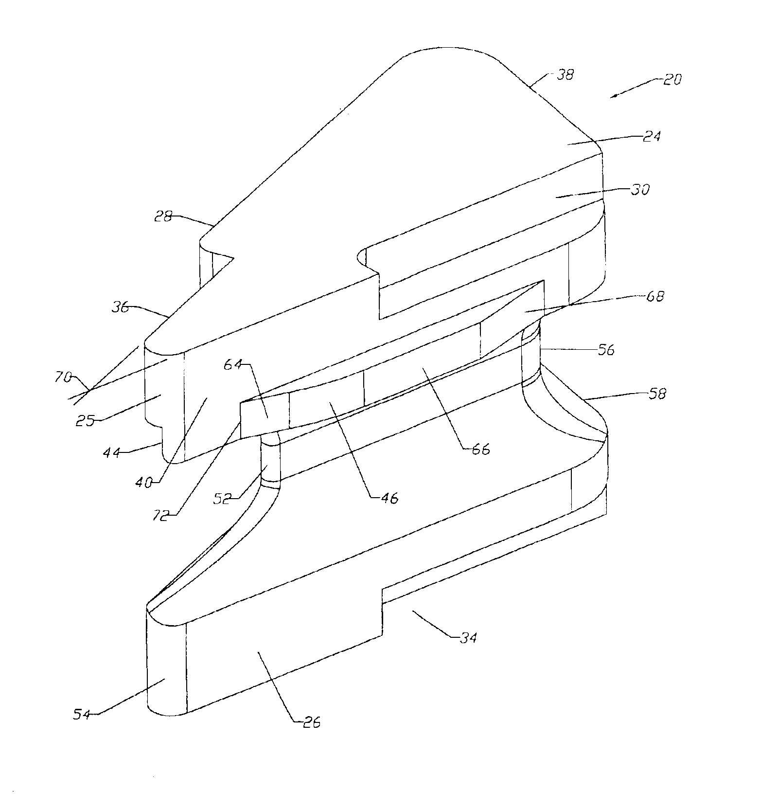
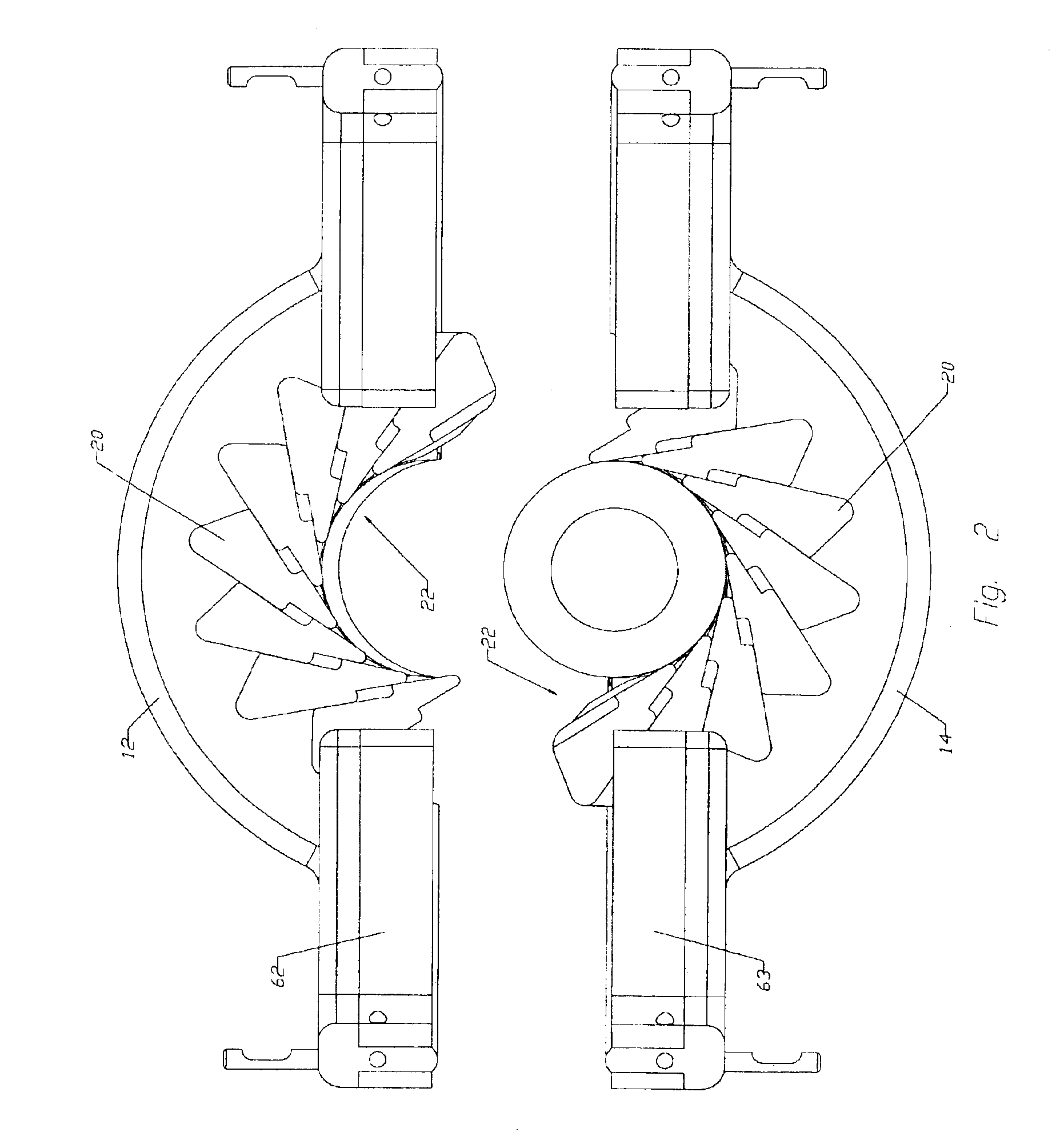
The BOP of the present invention provides for high sealing reliability, while also sealing with tubulars over a wide range of tubular ODs. The metal inserts are typically arranged in a circumferential and flange array. The inserts each have a generally triangular configuration, and are arranged to slide in an iris manner with respect to each other The number of cicumferentially spaced inserts provided will depend upon the sealing diameter requirements of the BOP. The inserts may be arranged in an array for expanding in either a clockwise or counterclockwise direction.
A related feature of the insert is that the opposite face of the triangular insert is angled from about 10° to about 30° with respect to a tangent to the bore, thereby providing a highly reliable BOP assembly with a relatively low diameter.

Problems solved by technology

Prior art BOPs have various disadvantages which have limited their acceptance in the oil and gas exploration and recovery industry.
Some of the limitations in prior art BOPs concern the large diameter of the blowout preventer, which ideally is as small as possible both in vertical height and in the overall diameter, while also reliably sealing against a wide range of tubular diameters.
Although BOPs that use metal inserts are able to withstand higher pressures than BOPs without such inserts, the metal inserts have difficulty with reliably sealing against a high pressure differential across the closed BOP.

Method used


Image

  • BOP assembly with metal inserts
  • BOP assembly with metal inserts
  • BOP assembly with metal inserts

Examples


Embodiment Construction

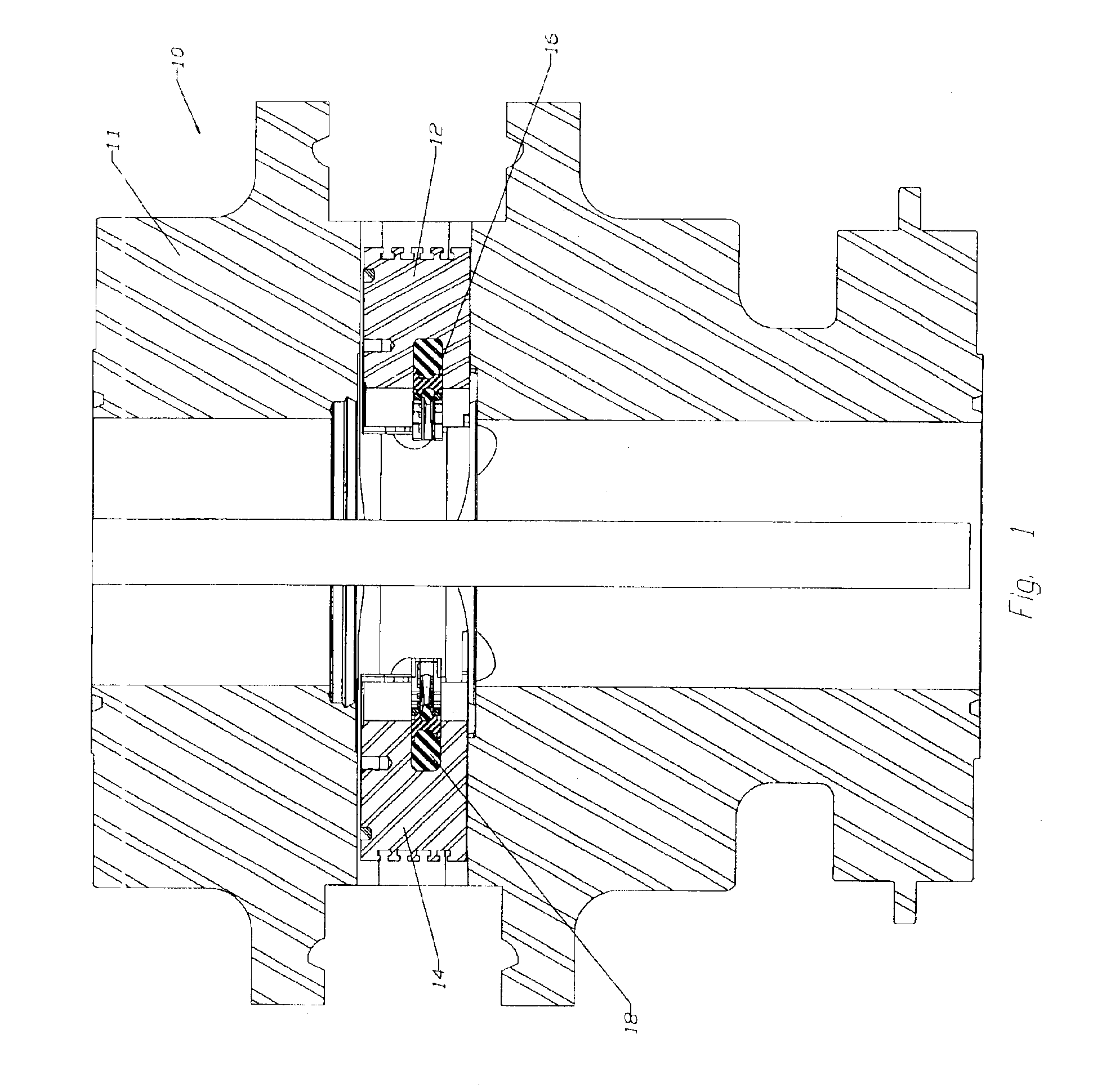
The BOP assembly 10 includes a housing 11 with a central bore for receiving a drill pipe DP and radially opposing ram block assemblies 12, 14 each including a rubber or elastomer material sealing assembly 16, 18 for sealing engagement with the drill pipe DP or other tubular passing through the BOP. Each of the sealing assemblies includes a plurality of inserts 20, as shown in FIGS. 2 and 3, with the inserts arranged within the sealing assembly to form an array 22 of metal inserts within each ram block assembly. The radially outward end of each ram block assembly is adapted for engagement with the end of a hydraulically powered ram (not shown). Conventional opposing rams for powering the rams are well known in the art, and are typically included within the BOP assembly. Suitable hydraulically powered rams are disclosed in the prior art patents discussed above, and are incorporated by reference herein.

The generally triangular shaped metal inserts 20 as shown in FIG. 3 cooperate with e...


PUM


Abstract

A blowout preventer assembly 10 includes opposed rams 12, 14, each including a rubber or elastomer sealing assembly 16, 18, with a plurality of inserts 20 forming an array 22 of metal inserts within each sealing assembly. Each insert has an upper body 24, a lower body 26, and a rib 50. Each upper and lower body includes a trailing face 36, a radially outward opposite face 38 and a leading face 40. An antiextrusion ledge 46 minimizes the extrusion gap between the OD of a tubular in the BOP and the leading face of the metal inserts in the array.

Description

FIELD OF THE INVENTIONThe present invention relates to a BOP assembly commonly used for sealing with oilfield tubulars. More particularly, this invention relates to improvements in the metal inserts provided within the seal mechanisms of the sealing assembly.BACKGROUND OF THE INVENTIONBlowout preventers used in hydrocarbon recovery operations have traditionally been manufactured with radially opposing rams that move inward to seal against the tubular, then move outward to let a tool joint pass by the BOP. Each sealing ram contains a relatively large elastomer for accomplishing the desired seal with both the tubular and with the opposing ram.In order to provide more reliable BOPs capable of withstanding higher pressure differentials, metal inserts have been provided within the elastomer of the BOP rams. U.S. Pat. No. 4,229,012 discloses a ram-type blowout preventer with metal inserts as shown in FIG. 3A. Metal plates are positioned above and below the sealing portions, and a pin exte...

Claims


Application Information

Patent Timeline
IPC IPC(8): E21B33/03E21B33/06
CPCE21B33/062
Inventor ARAUJO, RAUL
Owner VARCO SHAFFER
Learn More