Fishing reel component

a technology of reel components and reels, applied in the direction of reels, fastening devices, animal husbandry, etc., can solve the problem that the gap between the engagement portions of the engagement spring cannot be widened, and achieve the effect of preventing errors

Inactive Publication Date: 2005-02-22
SHIMANO INC
View PDF12 Cites 10 Cited by
  • Summary
  • Abstract
  • Description
  • Claims
  • Application Information

AI Technical Summary

Benefits of technology

An object of the present invention is to prevent errors in the assembly of the operation member to the engagement spring in fishing reel components that are capable of being detached from a shaft member with one touch.
The fishing reel component according to an eleventh aspect of the present invention is the component described in any of the first to ninth aspects, in which the shaft member is a knob shaft that is fixed to a tip of a handle arm of a dual bearing reel. Further, the component unit is a knob unit that is rotatably and detachably mounted to a handle shaft. Here, errors in the assembly of the components of the handle knob of the dual bearing reel can be prevented.

Problems solved by technology

Given this structure, there is a possibility that the pair of tapered portions of the operation member can be inadvertently inserted into the outer sides of the pair of engagement portions during assembly.
When the tapered portions are inserted into the outer sides of the pair of engagement portions of the engagement spring, the gap between the engagement portions of the engagement spring cannot be widened, even if the operation member is pushed.

Method used


Image

  • Fishing reel component
  • Fishing reel component
  • Fishing reel component

Examples


first embodiment

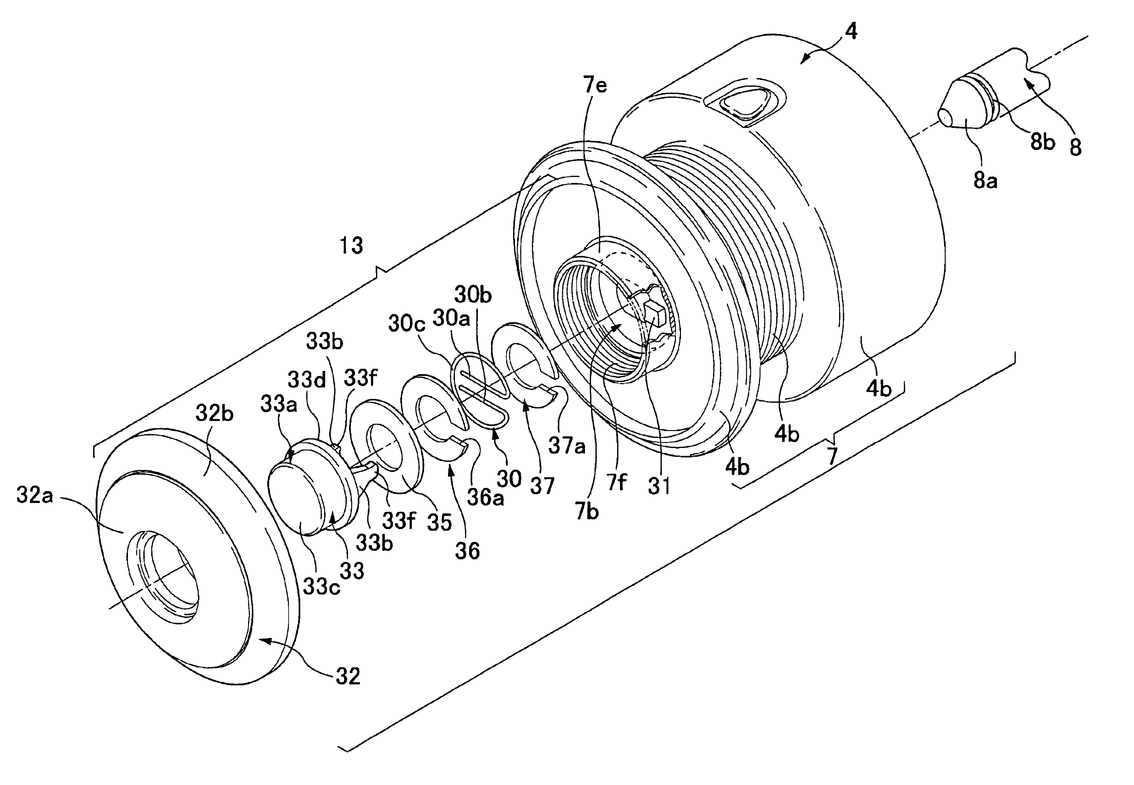
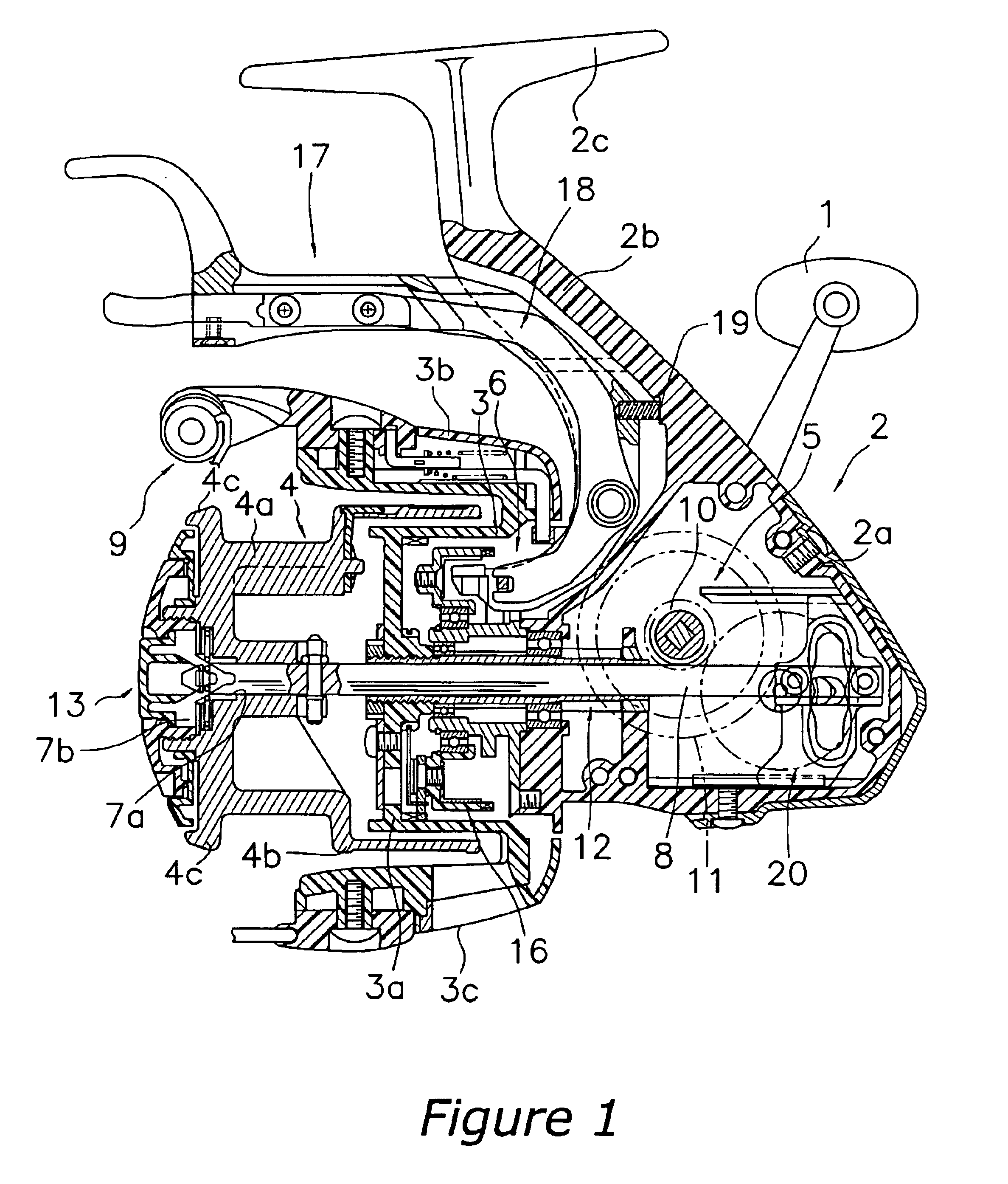
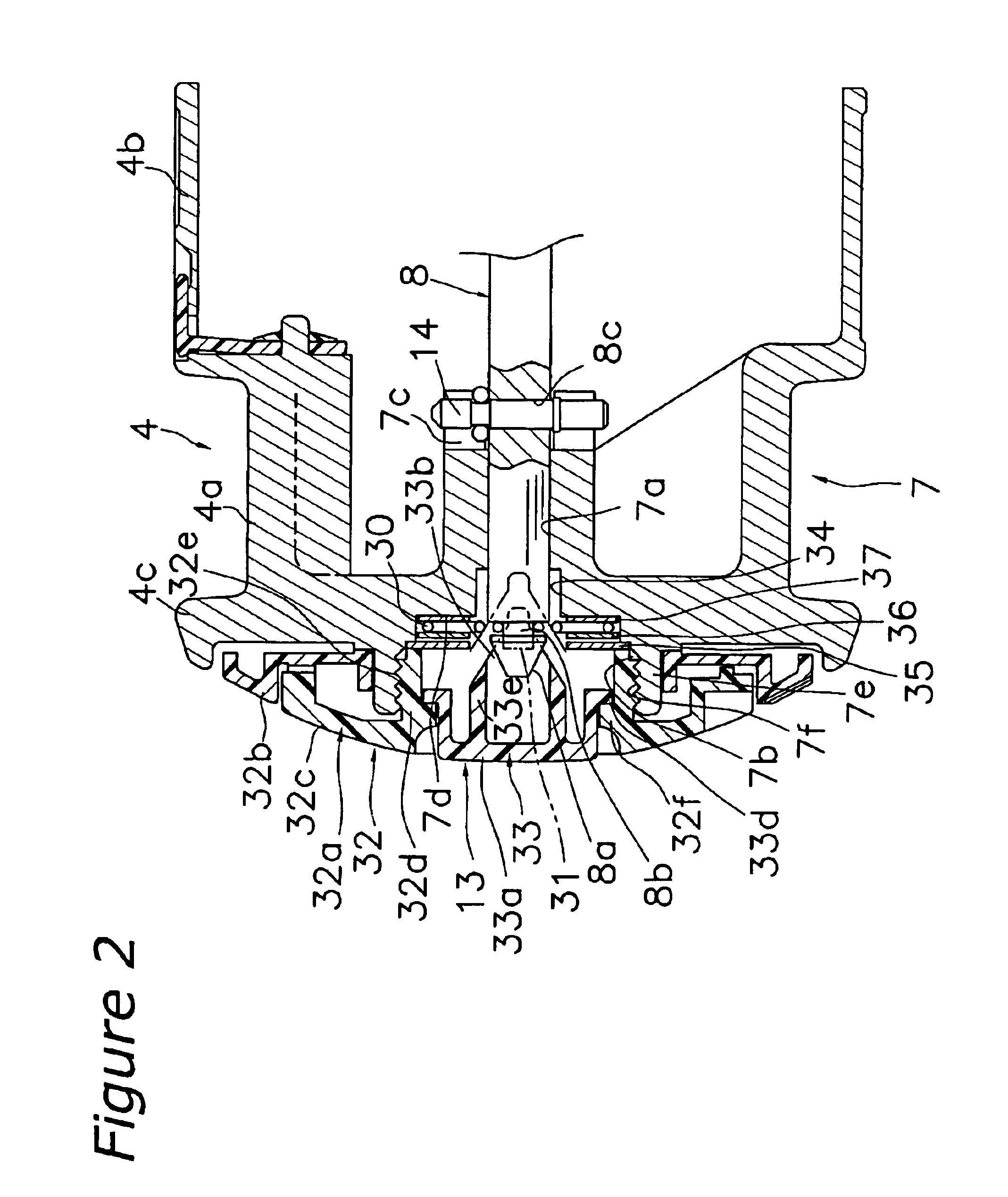
As shown in FIG. 1, a spinning reel according to the present invention is a lever brake type of reel which rotates and winds fishing line in a direction that is longitudinal to the fishing rod. The spinning reel includes a reel unit 2 that includes a handle 1, a rotor 3 that is rotatably supported on a front portion of the reel unit 2, and a spool 4 that is disposed on the front portion of the rotor 3 and around which fishing line is wound.

As shown in FIG. 1, the reel unit 2 is, for example, composed of a synthetic resin. The reel unit 2 includes an attachment portion 2c, a reel body 2a, and a leg portion 2b. The attachment portion 2c extends from the front to the rear of the reel unit 2 and is to be mounted to the fishing rod. The reel body 2a is disposed with a gap between the reel body 2a and the attachment portion 2c and includes a mechanism accommodation space in the interior of the reel body 2a. The leg portion 2b links the attachment portion 2c with the reel body 2a. The hand...

third embodiment

The positioning projection 71 and the engagement hole 74 are formed on a washer 75 identical or substantially identical to the washer 237 shown in the In addition, a cut-out is formed in the washer 76. The positioning projection 71 is slightly longer than the thickness of the engagement spring 59, and is shorter that the combined thicknesses of the engagement spring 59 and the washer 76.

A lid member 72 is screwed to the knob 58, and prevents the engagement spring 59 and the operation button 73 from falling out. The operation button 73 has a structure identical or substantially identical to the operation button 33 of the first embodiment, and includes tapered portions 73b. A description of the structure which prevents members from falling out and the structure of the operation button 73 will be omitted as they are identical or substantially identical to those of the aforementioned embodiment.

In this type of handle assembly 42, the operation button 73 will be pushed when the handle k...


PUM


Abstract

A spinning reel spool is detachable from a spool shaft having a tapered surface and an engagement groove. The spool includes a spool unit, an engagement spring, a positioning projection, a lid member, an operation button, and an engagement hole. The spool unit includes a circular mounting space. The positioning projection determines the rotational position of the engagement spring. The operation button is mounted in the lid member and can pass over the engagement groove. The operation button includes a pair of tapered portions that are disposed with the spool shaft therebetween such that the gap between the pair of engagement portions is widened by movement of the operation button in the axial direction. The engagement hole controls the rotational position of the operation button.

Description

BACKGROUND OF THE INVENTION1. Field of the InventionThe present invention generally relates to a fishing reel component. More specifically, the present invention relates to a fishing reel component detachable with one touch from a shaft member of a fishing reel, where the shaft member has having a tapered surface formed on its tip and an annular groove formed to the rear of the tapered surface.2. Background InformationFishing reel components that can be detached with one touch from a spool shaft (an example of a shaft member), are known in the prior art. An example of a fishing reel component is a spool for a spinning reel. For example Utility Model Application Publication No. H06-068447 discloses a fishing reel component that can be detached with one touch. Such conventional spool that is detachable with one touch is detachably mounted to a spool shaft, the spool shaft having a tapered surface formed on the tip thereof and an annular groove formed to the rear of the tapered surface...

Claims


Application Information

Patent Timeline
Patent Type & Authority Patents(United States)
IPC IPC(8): A01K89/01A01K89/00A01K89/015F16B21/18
CPCA01K89/0111A01K89/006A01K89/0113A01K89/01
Inventor KITAJIMA, KEIGO
Owner SHIMANO INC
Why Eureka
Try Eureka