
Restraining harness

a harness and occupant technology, applied in the field of chairs and seats, can solve the problems of preventing the occupant from moving freely, causing the occupant to be virtually unimpeded, and causing the occupant to be virtually unimpeded

Inactive Publication Date: 2005-02-22
MORRIS DANE MICHAEL
View PDF27 Cites 19 Cited by
  • Summary
  • Abstract
  • Description
  • Claims
  • Application Information

AI Technical Summary

Benefits of technology

In light of the problems associated with the known products for preventing prisoner movement in a vehicle, it is a principal object of the invention to provide a restraining harness that fixes a handcuffed prisoner in a predetermined location in a vehicle, usually in a spot where he may be further restrained by the factory-installed seat belts in the vehicle for maximum safety. The restraining harness further prevents the handcuffed prisoner from disengaging the factory-installed seat belts normally binding him in a seated position. In fact, a handcuffed prisoner is effectively prevented by the restraining harness from moving his entire upper body more than a few inches in any one direction. Thus, use of the restraining harness virtually eliminates the possibility of a prisoner escaping without the aid of others.
It is another object of the invention to provide a restraining harness of the type described that can be installed in virtually any vehicle with minimal effort using conventional tools. One embodiment of the restraining harness relies on the presence of a conventional child safety seat mount in a vehicle for securement. Use of the restraining harness is intuitive and can be accomplished with minimal training.
Still another object of the invention is to provide a fully adjustable restraining harness that can be easily engaged with, and quickly released from, a handcuffed prisoner of virtually any size. Either task can be accomplished by authorized personnel in a matter of seconds.
It is an object of the invention to provide improved elements and arrangements thereof in a restraining harness for the purposes described which is lightweight in construction, inexpensive to manufacture, and dependable in use.

Problems solved by technology

Because handcuffs only restrict the arms of a wearer, handcuffed prisoners sometimes move about the interior of automobiles and, as a result, cause injury to: themselves, the automobiles they are riding in, and the people charged with maintaining their custody.
Experience has shown that a determined prisoner in handcuffs can open the factory-installed seat belts in an automobile thus permitting him virtually unimpeded movement.
Unfortunately, these products have proven to be difficult to use and unsafe in emergencies when fast evacuation from a vehicle is required.
For these reasons, law enforcement agencies have not adopted such products for standard use.

Method used


Image

  • Restraining harness
  • Restraining harness
  • Restraining harness

Examples


Embodiment Construction

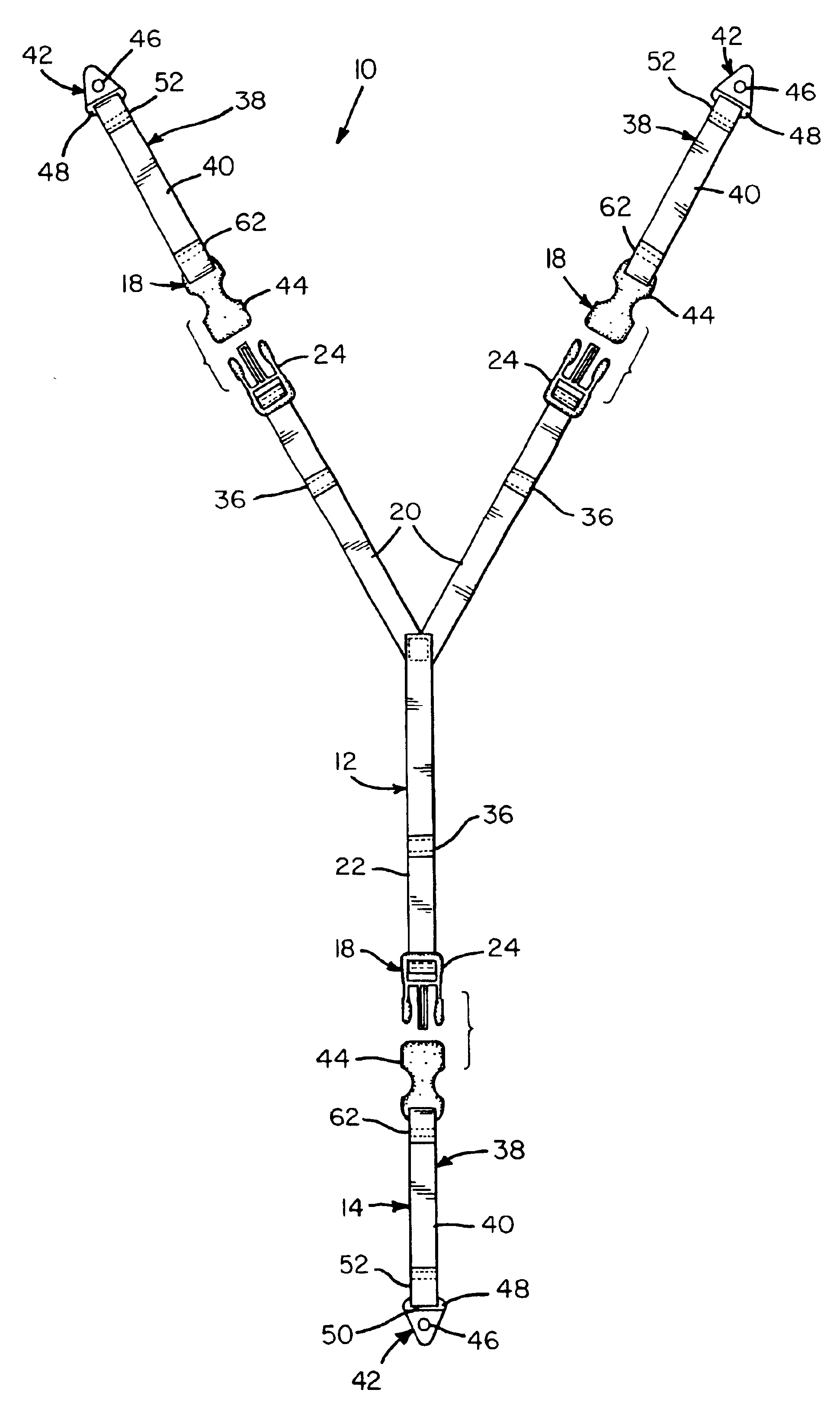
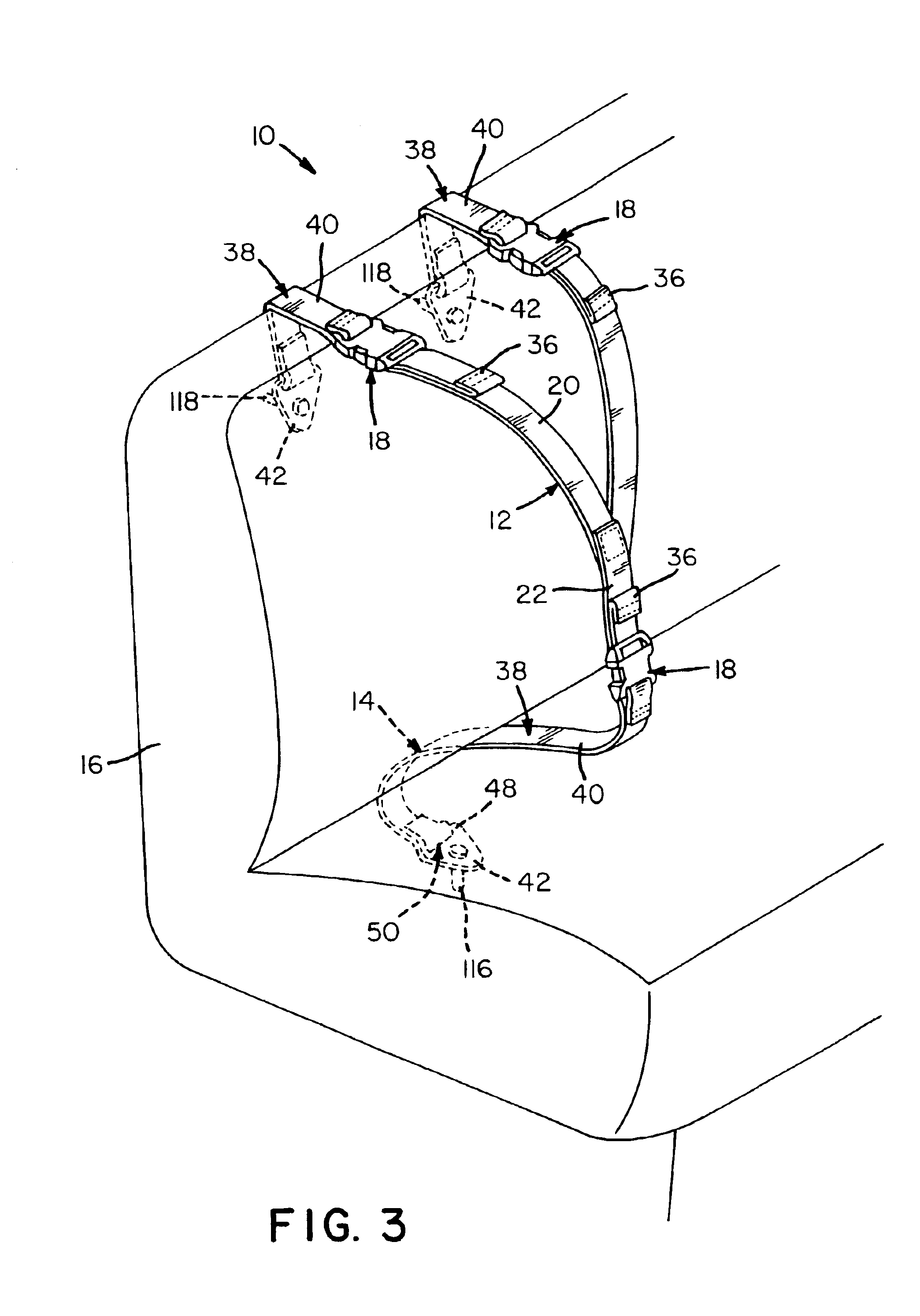
Referring now to the FIGS., a restraining harness in accordance with the present invention is shown at 10. Restraining harness 10 includes a torso binder 12 and an anchor assembly 14 for securing torso binder 12 adjacent a vehicle seat 16. A plurality of releasable fasteners 18 associated with torso binder 12 and anchor assembly 14 permit torso binder 12 to be rapidly attached and detached from seat 16 for ease in handling a handcuffed prisoner (not shown).

Torso binder 12 has a Y-shaped configuration for positioning over the shoulders and through the crotch of a prisoner being restrained thereby. This Y-shaped configuration is, preferably, obtained by sewing the bottoms of a pair of shoulder straps 20 to the top of crotch strap 22 such that shoulder straps 20 project upwardly and outwardly from crotch strap 22. To the free ends of straps 20 and 22 are secured the male components or portions 24 of releasable fasteners 18.

Each of the male components 24 includes a body 26 having an ali...


PUM


Abstract

A restraining harness for use in land vehicles including a torso binder and an anchor assembly for securing the torso binder adjacent a seat so as to restrain a handcuffed prisoner. A number of releasable fasteners associated with the torso binder and the anchor assembly permit the torso binder to be rapidly attached and detached from the torso binder.

Description

FIELD OF THE INVENTIONThe present invention relates generally to chairs and seats, and, more particularly, to occupant restraints used therewith.BACKGROUND OF THE INVENTIONAccording to a recent Justice Department report, the number of people held in U.S. prisons, jails and other correctional facilities now exceeds two million. On any given day, thousands of prisoners are being transported to and from these facilities. For short trips, automobiles are normally used as a means for transportation.While being transported in automobiles, prisoners are usually restrained by handcuffs binding their wrists together for the safety of all vehicle occupants. Because handcuffs only restrict the arms of a wearer, handcuffed prisoners sometimes move about the interior of automobiles and, as a result, cause injury to: themselves, the automobiles they are riding in, and the people charged with maintaining their custody. These injuries are, more often than not, the result of deliberate acts to escap...

Claims


Application Information

Patent Timeline
IPC IPC(8): A61F5/37B60R22/02B60R22/00
CPCA61F5/3776B60R22/02B60R2022/003
Inventor MORRIS, DANE MICHAEL
Owner MORRIS DANE MICHAEL
Learn More