Eureka AIR delivers breakthrough ideas for toughest innovation challenges, trusted by R&D personnel around the world.

Communications system

a communication system and communication technology, applied in the field of communication control, can solve the problems of not providing a generally accessible system, and achieve the effects of improving interaction efficiency, saving third party time, and faster provisioning of more complex services

Inactive Publication Date: 2005-02-15
TIME WARNER CABLE ENTERPRISES LLC
View PDF18 Cites 64 Cited by
  • Summary
  • Abstract
  • Description
  • Claims
  • Application Information

AI Technical Summary

Benefits of technology

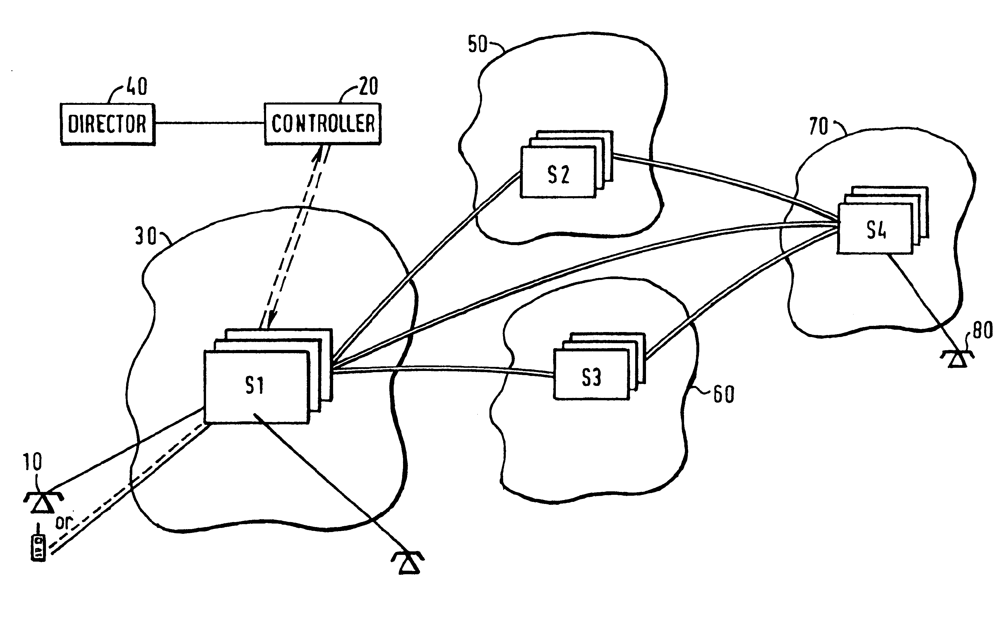
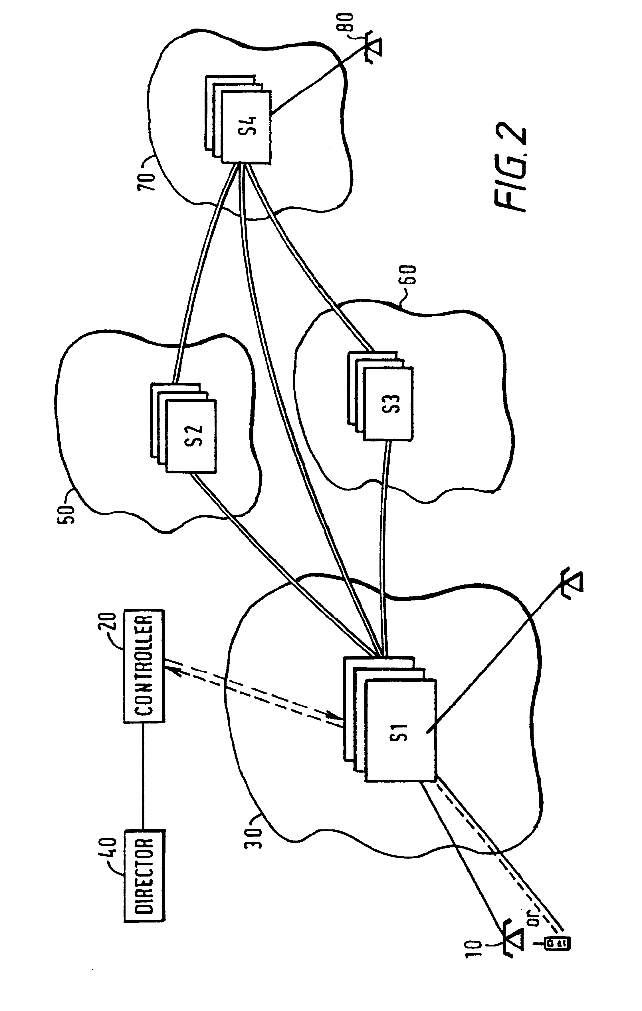
The third party can comprise at least one of a user, a subscriber, a communication service provider, and a communications network operator. Thus the present invention allows a user, a subscriber, or a service provider acting on behalf of a subscriber for example to control the way in which outgoing communications are processed i.e. routed on a call by call basis in order to select carriers which cost the least, without the need to add a dialling prefix for outgoing calls.
The processing to be carried out as a function of cost is dependent upon the directions from the third party and these can either be indirect i.e. the operator of the control means can set up the control means to operate in accordance with the wishes of the third party, thus saving the third party time, or direct access can be provided to the control means to allow the third party to set up the processing required, facilitating faster provisioning of more complex services or changes to service / routing options. Such a direct accessing facility can be provided by allowing a subscriber to dial in to the communication control means in order to set up the processing required. Of course suitable security measures will need to be taken with such a direct facility e.g. password verification, calling line identity verification, encryption, etc.
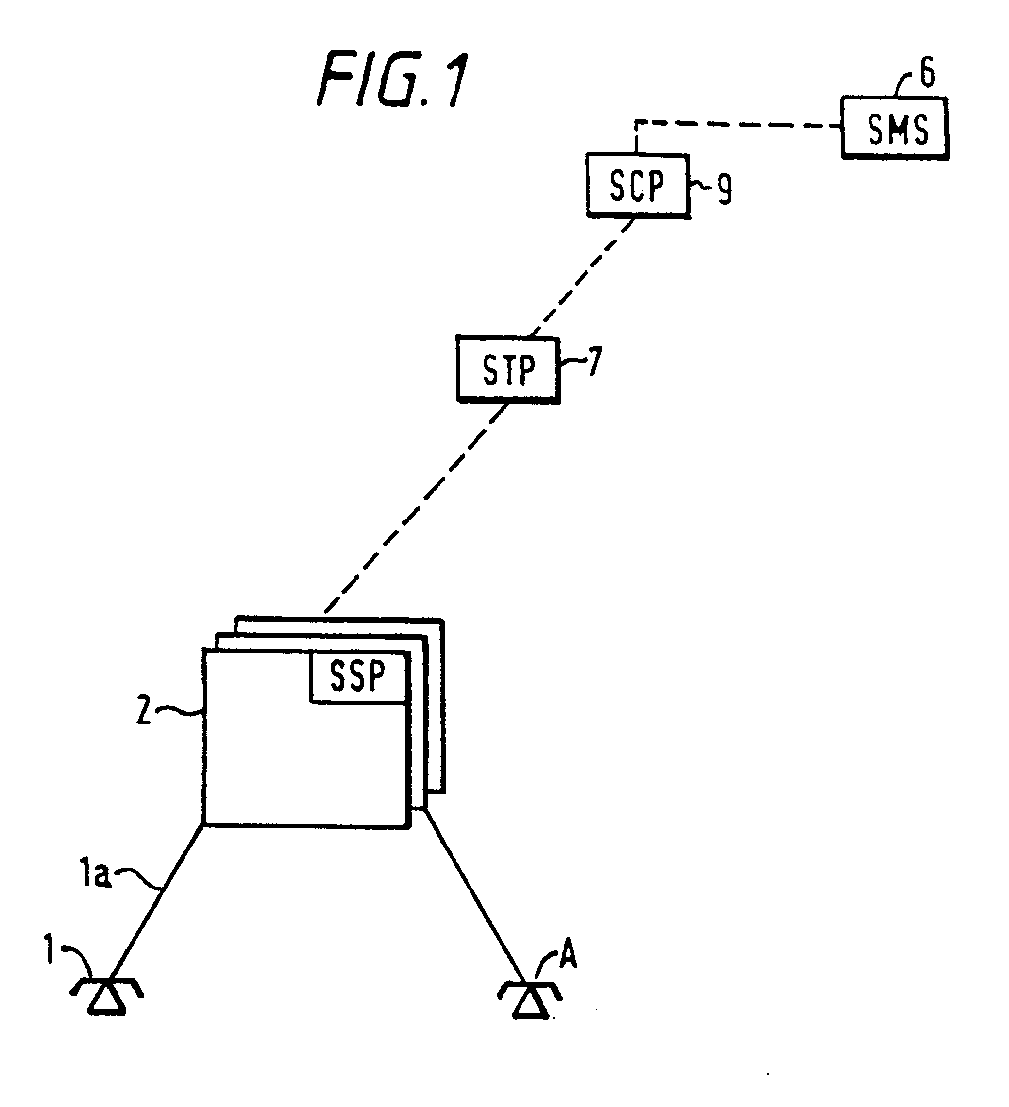
In one embodiment all of the communications control signals from calls associated with the subscriber are directed from the switching means to the control means, for simplicity of implementation. Alternatively, the switching means is programmed to identify particular communications to be processed by the control means so only these can be directed to the control means for processing. This would have the effect of increasing the efficiency of the interactions between the control means and the switching means, reducing the number of transactions and offering the potential for further cost reduction. The identification of the communications can, in an Advanced Intelligent Network (AIN) implementation, comprise any suitable AIN trigger point. The control means can include a database which is used for the processing of the communication signals. The database can include cost information for the possible carriers which can be used to route communication, and subscriber specific information.

Problems solved by technology

The disadvantage with this method is that the call-by-call selection of the carrier is made either within the Customer Premises Equipment (CPE), necessitating certain types of CPE and possibly necessitating communication links between the CPE and the inter-exchange carriers that could be used, or within the local exchange, putting the selection ability and range of carriers that could be offered within the control of the local exchange carrier.
As the number of alterative carriers increases, the first method becomes inefficient and restricts the number of customers where this method is economically viable, and the second method maintains the effective control within the local exchange carrier.
Although the prior art systems provide some form of control for a subscriber, they do not provide a generally accessible system whereby a subscriber can, whilst maintaining dialling parity, control the routing of their communication by control means that are independent of the local exchange carrier or mobile carrier to which they subscribe.

Method used


Image

  • Communications system
  • Communications system
  • Communications system

Examples


Embodiment Construction

In future telecommunications network architectures the concept of a call may be replaced by that of a session or other concept; in the Telecommunications Information Network Architecture (TINA) for example, the concept of a call is replaced by a ‘session’, and a query and response is replaced by a sequence of messages within the session). The invention encompasses such architectures. Similarly the concept of an originator is proposed to move to an ‘invoking party’ and a terminating party is proposed to move to an ‘invited party’.

It is understood by those skilled in the art that differing intelligent network standards exist, including the Bellcore AIN releases as well as the ITU IN standards, and that implementations of such standards are often partial in differing geographical regions and individual network operators. Many networks only use AIN / IN for specific services, and implementations of AIN / IN in many networks are to some degree proprietary. The descriptions hereinafter borrow...


PUM


Abstract

In a communication network where a subscriber is connected to switches in an originating carrier communications are routed to and / or from the subscriber via at least one communications carrier selected from a plurality of possible communications carriers. Communications control signals associated with outgoing and / or incoming communications are received from the switch at a controller external to the originating carrier. The communications control signals are processed at the controller in dependence upon directions from a third party using information on communications costs for each of the possible communications carriers to select at least one communications carrier for routing communications based on the information on communications cost to generate process communications control signals for routing the communications in accordance with the selection. Process communication control signals will then return to the switch in the originating carrier and the communications from and / or to the subscriber are switched to route the communications via the or each selected communications carrier in accordance with the process communications control signals.

Description

FIELD OF THE INVENTIONThe present invention relates to a method of controlling communications over a communications network and a communication control system.BACKGROUND TO THE INVENTIONIn a telecommunications network comprising a plurality of interconnected carrier networks, a subscriber is connected to a local loop provider who can actively control the access that the subscriber has to the networks. The provider of this local loop has been able to effectively control this ‘gateway’ to the subscriber to act as an effective tollgate to the subscriber. (Although generally fixed network examples are used, a very similar scenario exists for mobile network operators who operate a similar ‘tollgate’ for their subscribers). Over recent history there has been regulatory action to curb the power of the local loop providers. In the UK for example indirect access has been offered whereby a subscriber can prefix a dialled number with a ‘1XXX’ code to indicate which carrier the call is to be ro...

Claims


Application Information

Patent Timeline
Patent Type & Authority Patents(United States)
IPC IPC(8): H04Q3/64H04Q3/66H04Q3/00
CPCH04Q3/0029H04Q3/66H04Q2213/13095H04Q2213/13109H04Q2213/13138H04Q2213/13141H04Q2213/13541H04Q2213/13206H04Q2213/13213H04Q2213/13296H04Q2213/13345H04Q2213/13527H04Q2213/13176
Inventor STANFIELD, DAVID
Owner TIME WARNER CABLE ENTERPRISES LLC
Why Eureka
Eureka Blog
Learn More