
Fluids manipulation device with format conversion

a technology of format conversion and manipulation device, which is applied in the direction of positive displacement liquid engine, laboratory glassware, instruments, etc., can solve the problems of high risk of substrate contamination, high cost and difficulty in arranging a multitude of nozzles, and limiting elements of actuating means and media logistics, which are not miniaturized to the desired extent, and achieve cost-effective and accurate effects

Inactive Publication Date: 2005-02-15
HAHN SCHICKARD GESELLSCHAFT FUER ANGEWANDTE FORSCHUNG EV
View PDF31 Cites 23 Cited by
  • Summary
  • Abstract
  • Description
  • Claims
  • Application Information

AI Technical Summary

Benefits of technology

The present invention provides a fluid management apparatus that allows for the cost-effective and accurate application of microdroplets to a substrate in a predetermined pattern. The apparatus includes a substrate with fluid inlets and outlets arranged in a pattern, and fluid ducts connecting the inlets and outlets. The apparatus can be charged using standard automatic devices, and the invention provides a dispensing head that can produce biochips with high efficiency and low cost. The apparatus can also be used for format conversion between different microtiter plates. The invention allows for the simultaneous application of microdroplets onto a substrate, resulting in the production of reliable and low-cost biochips.

Problems solved by technology

In addition, the method is highly susceptible to contamination of the substrate and of the nozzles.
However, a major problem is that it is very expensive and rather difficult to arrange a multitude of nozzles, which are all supplied with different media, in parallel or in an array.
The limiting element here is actuating means as well as media logistics, which are not miniaturizable to the desired extent.
This synthesis method is by far the most expensive one among the methods mentioned, which allows, however, to produce the largest variety of analytes on a chip, in the order of magnitude of 100,000 different analytes per substrate.

Method used


Image

  • Fluids manipulation device with format conversion
  • Fluids manipulation device with format conversion
  • Fluids manipulation device with format conversion

Examples


Embodiment Construction

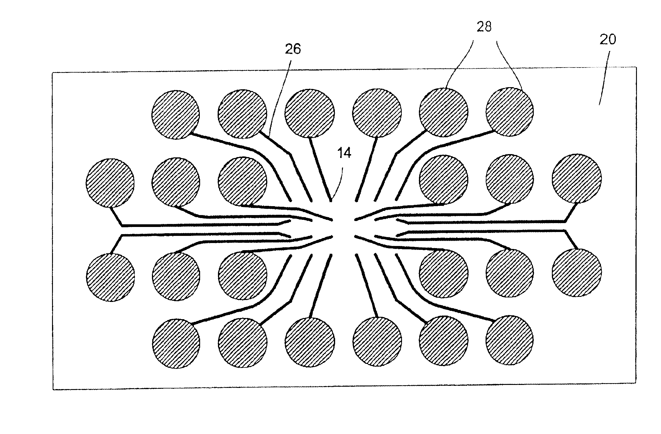
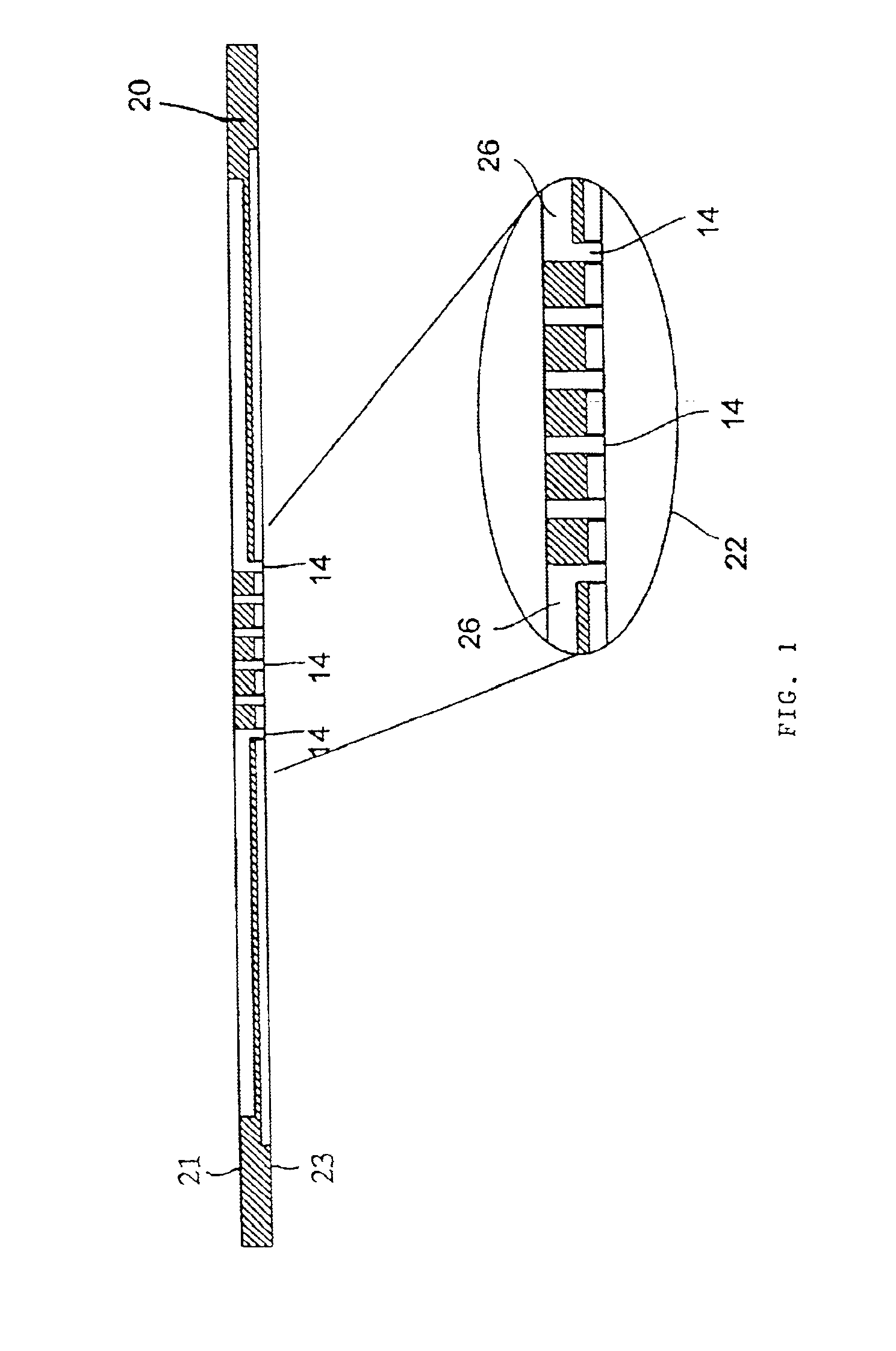
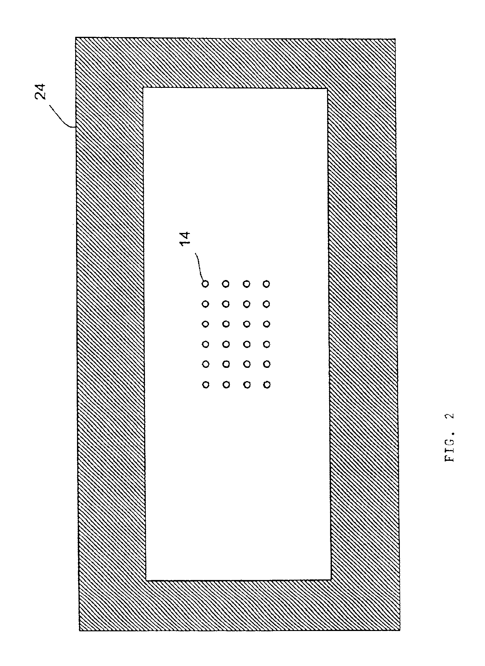
With reference to the figures, preferred embodiments of the present invention with regard to a dispensing head will be described in more detail below. However, it is evident that the principles explained may also apply, in the same manner, for other fluid management apparatus, to example means for format conversion between microtiter plates having different raster schemes.

With reference to FIGS. 1 to 3, a preferred embodiment of the fluid management apparatus in accordance with the invention, which may be a dispensing head, will be further explained below. The dispensing head may be a chip, for example, which has been produced using the methods of silicon micromechanics. Alternatively, the dispensing head may be formed from a plastic or a polymer using an injection molding technique. Further, the dispensing head may consist of a silicon-glass compound, a metal or a ceramic.

A diagrammatic cross-sectional view of such a chip, i.e. a fluid management apparatus in accordance with the in...


PUM

PropertyMeasurementUnit
widthaaaaaaaaaa
diameteraaaaaaaaaa
mutual distanceaaaaaaaaaa

Abstract

A fluid management apparatus includes a substrate having a first surface and a second surface opposite to the first surface. A plurality of fluid inlets, which are preferably media reservoirs, are formed in a first pattern in the first surface of the substrate. A plurality of fluid outlets, which are preferably nozzles, are arranged in a second pattern, which is different from the first pattern, in the second surface of the substrate. A plurality of fluid ducts formed in the substrate for connecting respective fluid inlets with respective fluid outlets are provided so that a format conversation from the fluid inlets to the fluid outlets is effected. The fluid outlets have opening cross-sections smaller than that of the fluid inlets. Furthermore, the fluid inlets may be arranged in the raster scheme of microtiter plates.

Description

BACKGROUND OF THE INVENTION1. Field of the InventionThe present invention relates to a fluid management apparatus which provides format conversion between a plurality of fluid inlets and a plurality of fluid outlets and is suitable, for example, for use in a dispensing head.The fluid management apparatus in accordance with the invention can be advantageously used, for example, in the dispensing head of an apparatus for applying at least one microdroplet to a substrate, with which a plurality of microdroplets can be applied to a substrate. In particular, the fluid management apparatus in accordance with the invention is suitable for being used in the production of so-called biochips, in which a plurality of different analytes are applied to a substrate in order to detect a different substances in an unknown sample. In addition, the present invention is suitable for implementing a format conversion between microtiter plates having different raster dimensions.The increasing decryption ...

Claims


Application Information

Patent Timeline
Patent Type & Authority Patents(United States)
IPC IPC(8): B01L3/02B01J19/00F04B19/00G01N35/10G01N33/53B01J4/00C40B60/14G01N1/00G01N1/28G01N33/48G01N33/566G01N37/00
CPCB01J19/0046F04B19/006G01N35/1067B01L3/0268B01J2219/00378B01J2219/00527B01J2219/00605B01J2219/00659Y10T436/2575C40B60/14G01N2035/1041G01N2035/1069
Inventor ZENGERLE, ROLANDHEY, NICOLAUSGRUHLER, HOLGERFREYGANG, MICHAELMUELLER, MARTIN
Owner HAHN SCHICKARD GESELLSCHAFT FUER ANGEWANDTE FORSCHUNG EV
Learn More