
Self-mode-stirred microwave heating for a particulate trap

a particulate trap and self-mode technology, which is applied in the direction of colloidal chemistry, machines/engines, separation processes, etc., can solve the problems of less than satisfactory combustion of particulates in the particulate trap, excessive temperature rise, thermal runaway, etc., and achieve the effect of removing particulate buildup

Inactive Publication Date: 2005-02-15
GM GLOBAL TECH OPERATIONS LLC
View PDF9 Cites 20 Cited by
  • Summary
  • Abstract
  • Description
  • Claims
  • Application Information

AI Technical Summary

Benefits of technology

The present invention is a method and apparatus for regenerating a diesel particulate trap using microwaves. The invention utilizes microwave energy to initiate the burn-off of particulates and remove the buildup of particles in the trap. The invention includes a particulate trap with microwave-absorbing materials placed at select locations in the trap. The microwaves are incident upon the absorbent materials and generate heat that ignites and burns off the particles. The invention also includes a self-mode-stirring (SMS) effect, where the materials absorb microwaves and the resulting heat causes a stirring effect that promotes uniform regeneration of the trap. The invention further includes materials with high-loss tangents that absorb microwaves and produce the SMS effect, as well as materials that exhibit a sharp decrease in loss tangent above a critical temperature to avoid thermal runaway conditions.

Problems solved by technology

As trapped material accumulates in the particulate trap, resistance to flow through the particulate trap increases, generating backpressure.
Particulate combustion in a diesel particulate trap by these past practices has been found to be difficult to control and may result in an excessive temperature rise.
Analogous problems with using microwaves to heat a particulate trap in automotive applications also exist.
Only portions of a microwave particulate trap may be heated when exposed to microwaves, leading to thermal runaway and less than satisfactory combustion of particulates in the particulate trap.
Mechanical mode-stirring and the use of multiple microwave frequencies are not practical solutions in automotive microwave heating applications.

Method used


Image

  • Self-mode-stirred microwave heating for a particulate trap
  • Self-mode-stirred microwave heating for a particulate trap
  • Self-mode-stirred microwave heating for a particulate trap

Examples


Embodiment Construction

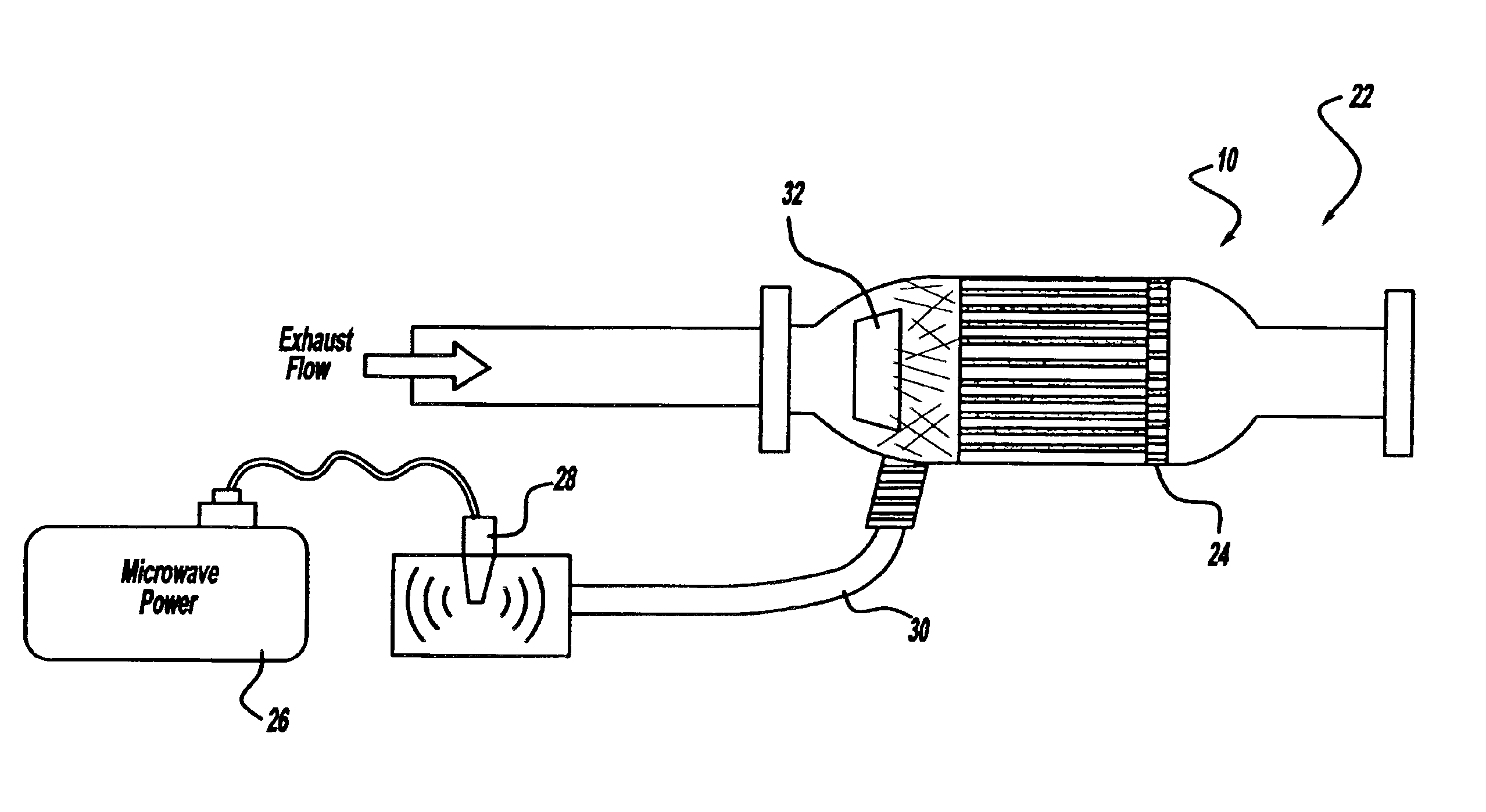
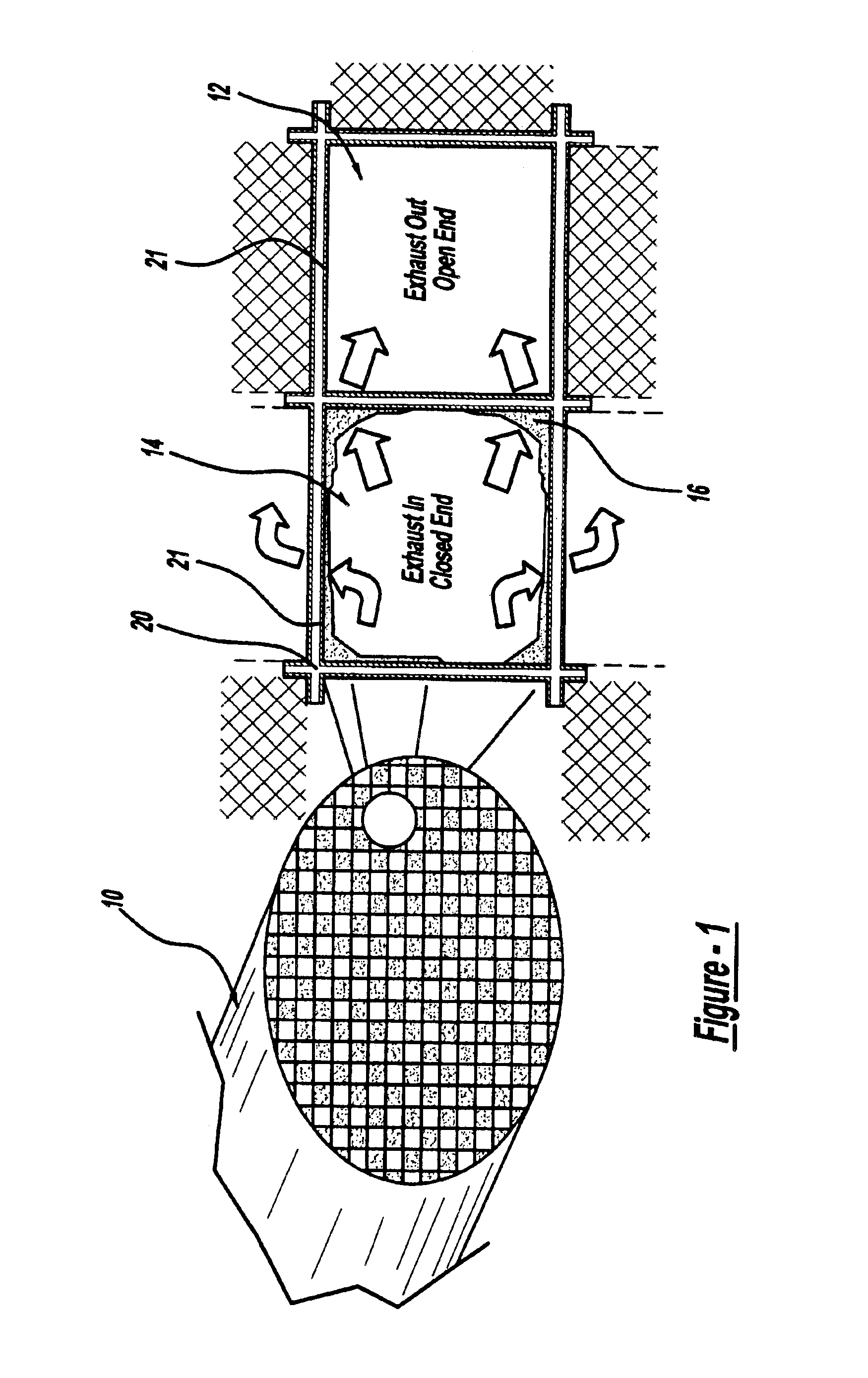
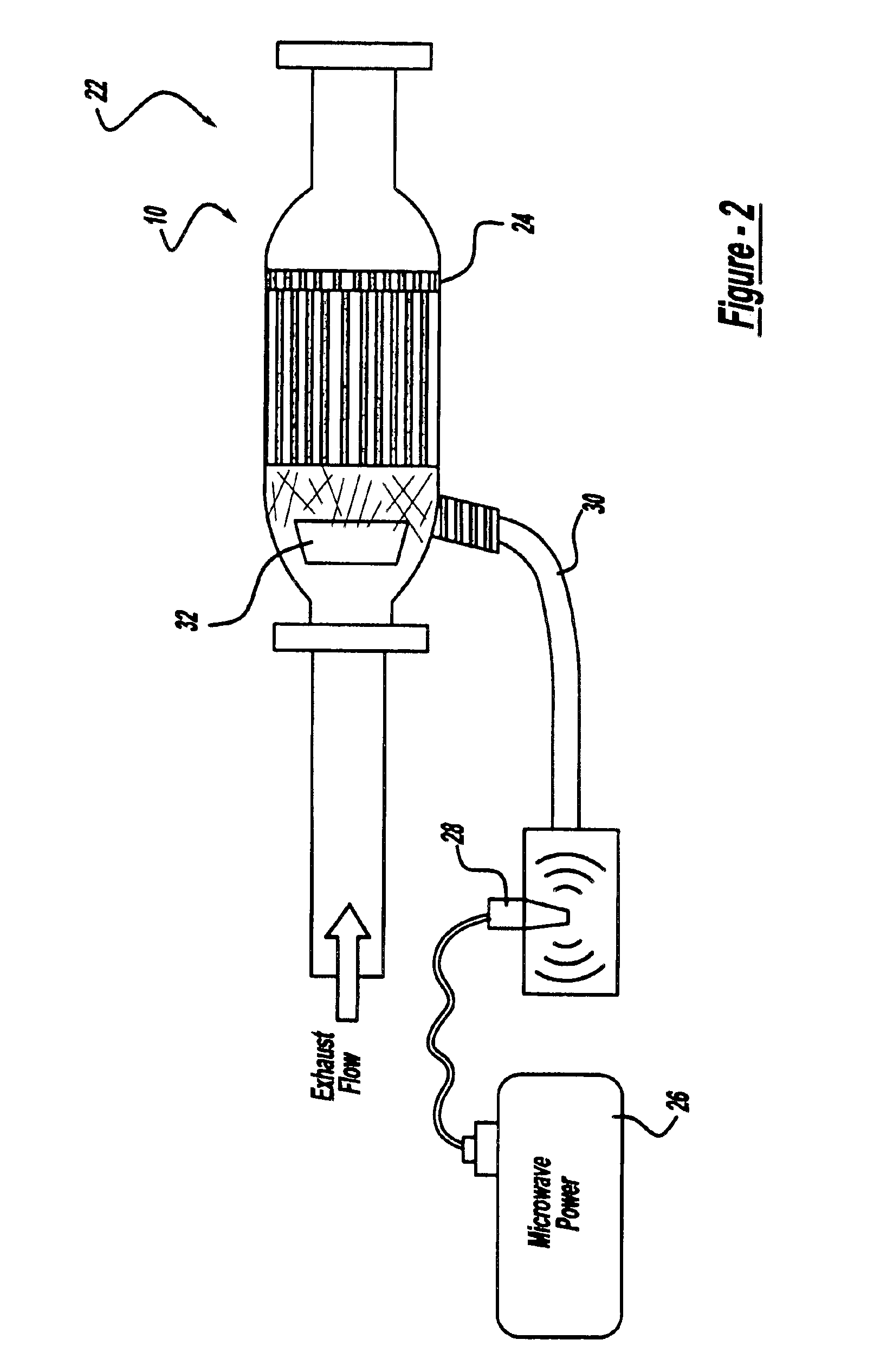
FIG. 1 is a diagrammatic drawing of a typical wall flow monolith particulate trap 10“particulate trap” used in diesel applications. The particulate trap 10 includes alternating closed cells / channels 14 and open cells / channels 12. Exhaust gases such as those generated by a diesel engine enter the closed end channels 14, depositing particulate matter 16 and exit through the open channels 12. The walls 20 of the particulate trap are preferably composed of a porous ceramic honeycomb wall of cordierite material, but any ceramic honeycomb material is considered within the scope of the present invention. The walls 20 of the particulate traps in the preferred embodiment are coated with materials 21 having SMS properties and decreasing loss tangent beyond the Curie temperature. In alternate embodiments of the present invention, SMS materials may be configured as walls or end plugs in the particulate trap 10. The SMS materials include, but are not limited to, magnetic ferrites having the gene...


PUM

PropertyMeasurementUnit
microwave transparentaaaaaaaaaa
Curie temperatureaaaaaaaaaa
microwave-absorbingaaaaaaaaaa

Abstract

A method and apparatus for initiating regeneration in a particulate trap including the steps of locating self-mode-stirring microwave-absorbing material in the particulate trap in areas that particulates build up, generating microwaves, absorbing microwaves with the microwave-absorbing material, and controlling the microwaves to initiate a burn-off of particulates.

Description

TECHNICAL FIELDThe present invention relates to a diesel particulate trap. More specifically, the present invention relates to a method and apparatus for regenerating a diesel particulate trap using microwave radiation and materials with self-mode-stirring properties.BACKGROUND OF THE INVENTIONIncreased government regulation has reduced the allowable levels of particulates generated by diesel engines. The particulates can generally be characterized as a soot that is captured by particulate filters or traps. Present particulate filters or traps contain a separation medium with tiny pores that capture particles. As trapped material accumulates in the particulate trap, resistance to flow through the particulate trap increases, generating backpressure. The particulate trap must then be regenerated to burn off the particulates / soot in the particulate trap to reduce the backpressure and allow exhaust flow through the particulate trap. Past practices of regenerating a particulate trap util...

Claims


Application Information

Patent Timeline
Patent Type & Authority Patents(United States)
IPC IPC(8): F01N3/023F01N3/028
CPCF01N3/028Y10S55/05
Inventor WILLIAMSON, TODKIRBY, KEVIN W.PHELPS, AMANDA
Owner GM GLOBAL TECH OPERATIONS LLC
Learn More