Method and device for determining a future travel-path area of a vehicle

Inactive Publication Date: 2005-02-08
ROBERT BOSCH GMBH
View PDF19 Cites 99 Cited by
  • Summary
  • Abstract
  • Description
  • Claims
  • Application Information

AI Technical Summary

Benefits of technology

The present invention provides a method and a device for reliably determining a future travel-path area of a first vehicle. According to the present invention, this travel-path area is able to be determined reliably and in a timely fashion, especially when vehicles traveling ahead have been detected for the first time.
Certain embodiments of the present invention provide that the future travel-path area is determined on the basis of measuring data which actually lie in the forward field of the controlled vehicle, and that these data are projected in the direction of the first vehicle's own position. In place of an estimation based on extrapolating an instantaneous situation, the situation actually existing in the forward field of the vehicle is evaluated. In this manner, it is especially possible to detect in a timely fashion the beginning or end of a curve. As a result, the error rate is significantly reduced compared with previously known methods. Further, the present invention is independent of particular infrastructure conditions, such as specially provided reflectors on the road edge. However, if appropriate reflectors are present, they can be taken into account accordingly. Furthermore, the present invention can be realized without special expense in a vehicle which is equipped with an adaptive speed regulating system, in particular without requiring an additional image pick-up and image valuation unit.

Problems solved by technology

One fundamental problem in systems of this type, in view of contemporary traffic patterns, is an automatic decision as to which vehicle of a plurality of vehicles traveling ahead is relevant, or most relevant, for the speed or distance control system.
This decision is particularly challenging when the road on which the controlled vehicle is moving is multi-lane and curvy.
However, this type of prediction does not function in the case of curves or lane changes.
A more complex case, which nevertheless delivers sufficient results for wide areas, is to assume a course having a constant curvature.
Therefore, here too, errors arise in response to every change of course, for example, in driving into or out of curves.
However, the limits of this method depend on how up-to-date and precise the available maps are and on the capacity of the system to determine in each case the current position of the vehicle.
The prediction may be unreliable in construction zones or on new roads.
However, according to the publication, little is known regarding the quality and reliability of this method.
However, the method described here can only be used if suitable reflectors are actually present on both sides of the road, and is therefore dependent on infrastructure conditions.

Method used


Image

  • Method and device for determining a future travel-path area of a vehicle
  • Method and device for determining a future travel-path area of a vehicle
  • Method and device for determining a future travel-path area of a vehicle

Examples


Embodiment Construction

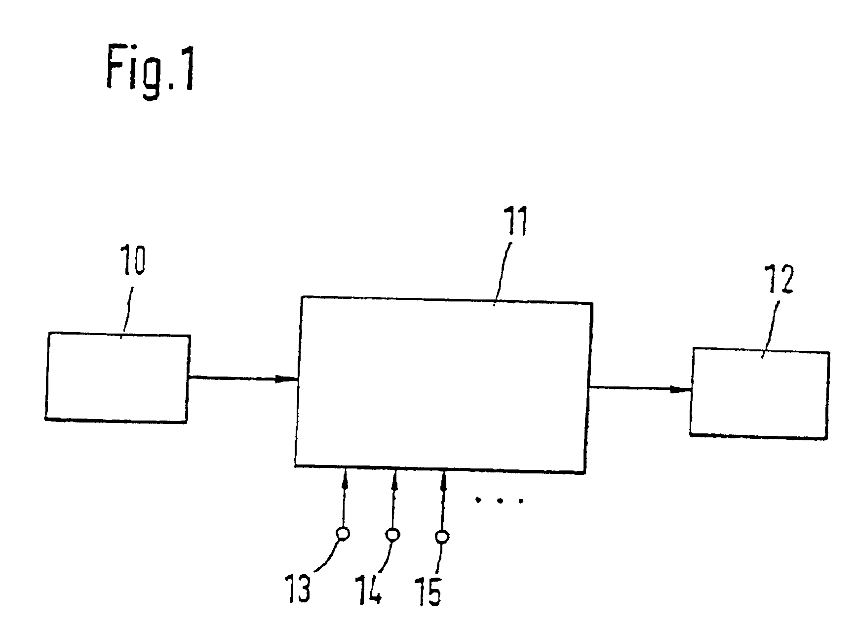
FIG. 1 shows a device for carrying out the method according to the present invention. A distance sensor 10, for example, a radar or a laser sensor, is connected to an evaluation and control unit 11. Evaluation and control unit 11 receives numerous further signals, of which, by way of example, an input 13 for the vehicle's own speed, an input 14 for a steering angle, and an input 15 for a yaw rate are depicted here. Furthermore, evaluation and control unit 11 is connected to one or a plurality of actuators 12. The entire device is installed in a first vehicle. Using distance sensor 10, in accordance with conventional methods, vehicles traveling ahead, oncoming vehicles, as well as stationary objects on, and on both sides of, the roadway are detected. Corresponding measuring data are pre-processed and are supplied to evaluation and control unit 11. The latter, in accordance with the method described below, determines at least one future travel-path area of the first vehicle. In the co...


PUM


Abstract

A method and a device are described for determining a future travel-path area of a first vehicle, which is furnished with a distance sensor. In this context, using the distance sensor at pre-established or selectable time points, at least relative positions are determined of at least one vehicle traveling ahead with respect to the first vehicle. At least these determined relative positions are stored in at least one storage device. These relative positions, stored in the storage device, constitute in each case a course path of the corresponding vehicle traveling ahead. The future travel path area of the first vehicle is determined at least on the basis of the course path of the vehicle traveling ahead. The course path of the vehicle traveling ahead is projected in the direction of the position of the first vehicle.

Description

FIELD OF THE INVENTIONThe present invention relates to a method and a device for determining a future travel-path area of a motor vehicle. It can be applied, for example, in an adaptive speed or distance control of a vehicle, in an adaptive headlight leveling adjustment, or simply in detecting critical situations. The vehicle is furnished with at least one sensor, which can detect, or at least determine the position of, vehicles traveling ahead and stationary objects in the forward field of the vehicle. Sensors of this type can be configured, for example, as radar, laser, or video sensors. The present invention can be used in connection with an adaptive speed or distance control system of a vehicle.BACKGROUND INFORMATIONIn past years, numerous publications have appeared, which deal with an automatic control system for the speed of a motor vehicle while taking into consideration the distance with respect to vehicles traveling ahead. Systems of this type are frequently termed Adaptive...

Claims


Application Information

Patent Timeline
IPC IPC(8): B60K31/00G01C21/26G08G1/16B60K31/02
CPCB60K31/0008B60W30/16G08G1/16G01C21/26Y02T10/84G05D2201/0213G08G1/165G08G1/166G08G1/167B60W30/18145G05D1/02
Inventor MICHI, HARALDSCHERL, MICHAELLICHTENBERG, BERNDUHLER, WERNER
Owner ROBERT BOSCH GMBH
Why Eureka
Try Eureka