
Electronic control system for torque distribution in hybrid vehicles

a technology of electric torque control and hybrid propulsion, which is applied in the direction of electric energy vehicles, internal combustion piston engines, analogue computers, etc., can solve the problems of affecting the performance of affecting the performance of the vehicle, and involving a considerable effort of the car manufacturer, so as to improve the performance of the hybrid propulsion vehicle

Active Publication Date: 2005-02-08
STMICROELECTRONICS SRL
View PDF15 Cites 38 Cited by
  • Summary
  • Abstract
  • Description
  • Claims
  • Application Information

AI Technical Summary

Benefits of technology

An object of the present invention is to provide an electronic torque control and distribution system, particularly for hybrid propulsion vehicles, having such structural and functional characteristics that overcome the limits of the prior art approaches discussed above by improving the hybrid propulsion vehicle performances and allowing smaller dimension propulsion systems to be formed.

Problems solved by technology

The growing interest shown by the international community for the decrease of air pollutants has led to the issuing of more and more severe regulations concerning automobile vehicle polluting emissions.
In the future, compliance with these regulations will involve a considerable effort by car producers in developing low emission vehicles.
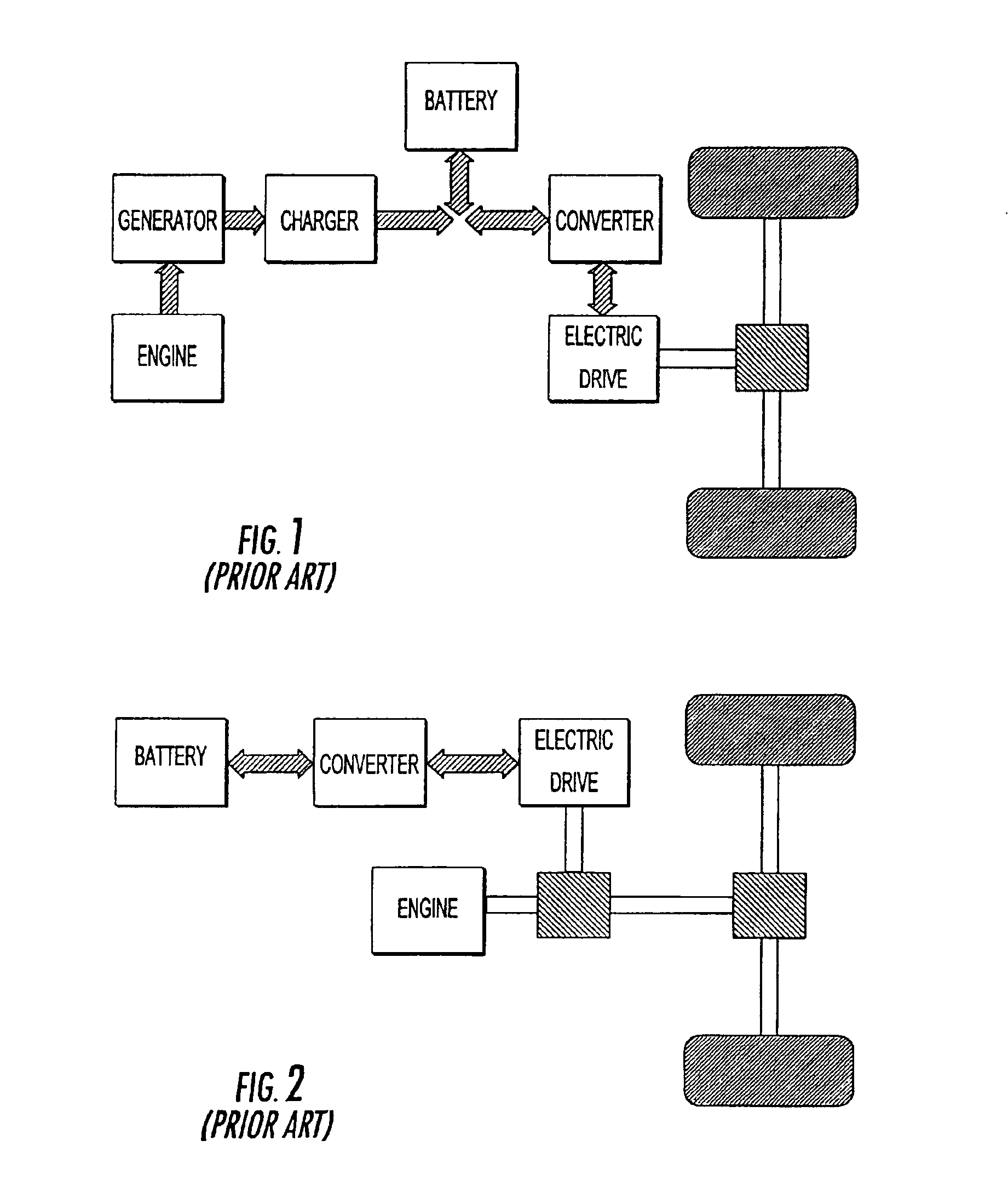
The drawbacks of this configuration are represented by the batteries which, having to be sized according to the electric machine rating, will be characterized by considerable size and weight, negatively affecting the vehicle performances. FIG. 1 shows in schematic blocks the structure of a hybrid propulsion vehicle of the previously described series type.
In the series configuration hybrid system the internal combustion engine only functions for the battery charge, therefore the high energy density of fossil fuels cannot be exploited.
Moreover, the high weight of the storage batteries causes a considerable increase in the vehicle inertia and this damages the equal power performances.
Also, the need to use two different electric machines, the one for the drive and the other for the storage battery recharge, increases the system complexity to the detriment of reliability.
The torque distribution methods according to the prior art do not ensure a global optimization of power output but only an optimization linked to contingent situations.
Nevertheless, this approach is difficult to implement and it would not lead to particularly interesting results from an industrial point of view.

Method used


Image

  • Electronic control system for torque distribution in hybrid vehicles
  • Electronic control system for torque distribution in hybrid vehicles
  • Electronic control system for torque distribution in hybrid vehicles

Examples


Embodiment Construction

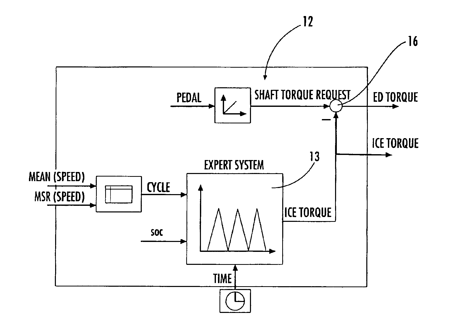
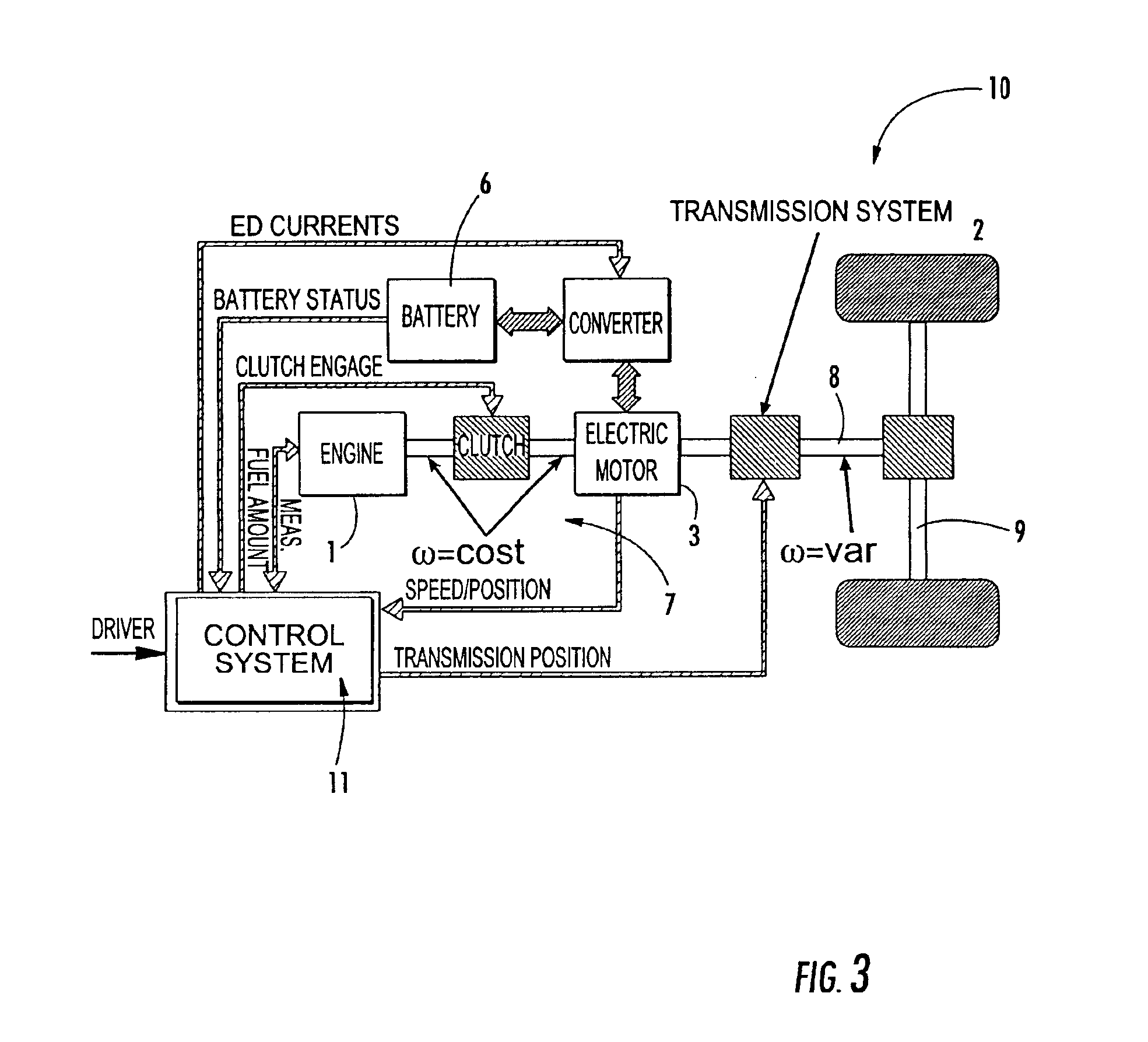
With reference to the drawings, and particularly to the examples of FIGS. 3 and 4, a vehicle 10 equipped with a parallel configuration hybrid propulsion system 7 will now be described. The electronic torque control and distribution system 11 formed according to the present invention is applied to the vehicle 10. Advantageously, the hybrid configuration of FIG. 3 is capable of combining the advantages of the two main types (series and parallel) of hybrid vehicles, as a result of an innovative management of power output.

From a classification point of view, the configuration according to the present invention can be incorporated in the parallel hybrid system types, in terms of both performance and size. In fact, as shown in FIG. 4, the vehicle 10 comprises an electric engine 3 which is drive assisted by an internal combustion engine 1. The internal combustion engine 1 is fuel fed by a tank 5 conventionally provided in the vehicle 1. Similarly, the electric engine 3 is powered by storag...


PUM


Abstract

An electronic torque control and distribution system is provided for a hybrid propulsion vehicle. The drive thrust of the hybrid propulsion vehicle is distributed between an electric engine and an internal combustion engine through a transmission system. The transmission system delivers the torque of both engines to the vehicle wheels. The electronic torque control and distribution system is slaved to a control unit, and includes a controller for incorporating a fuzzy logic processor to predict through soft computing techniques the torque contributions of the electric engine and of the internal combustion engine. A sensor estimates the vehicle polluting emissions. The controller and the sensor are both connected to the control unit.

Description

FIELD OF THE INVENTIONThe present invention relates to an electronic torque control and distribution system for hybrid propulsion vehicles. More specifically, the present invention relates to a hybrid propulsion vehicle wherein the drive thrust is distributed between an electric engine and an internal combustion engine through a transmission system delivering the torque of both engines to the vehicle wheels and being slaved to a control unit.BACKGROUND OF THE INVENTIONThe present invention is an improvement of what has been described in European Patent Application No. 01830645.6, which is incorporated herein by reference and is assigned to the current assignee of the present invention. The growing interest shown by the international community for the decrease of air pollutants has led to the issuing of more and more severe regulations concerning automobile vehicle polluting emissions.In particular, the European Union plans to implement within 2005 severe restrictions on exhaust emis...

Claims


Application Information

Patent Timeline
IPC IPC(8): B60K6/04B60K6/02B60K6/00G06F7/00B60K6/48B60K6/543B60W10/06B60W20/00
CPCB60K6/48B60K6/543B60W10/06B60L2240/486B60W20/00Y10S903/918B60W2550/147B60W2710/105Y02T10/6221Y02T10/84B60W2510/244B60W50/0097B60W2552/35Y02T10/40Y02T10/62B60W2510/0657B60W2510/242
Inventor CORCIONE, GIUSEPPE ESPOSITORIZZOTTO, GIANGUIDOVITALE, GIANLUCANOVIA, TOMMASO
Owner STMICROELECTRONICS SRL
Learn More