
Micro structure stent configurations

Inactive Publication Date: 2005-02-08
BOSTON SCI SCIMED INC
View PDF5 Cites 63 Cited by
  • Summary
  • Abstract
  • Description
  • Claims
  • Application Information

AI Technical Summary

Benefits of technology

The preferred stents having a micro structure in accordance with the present invention will also have a wall thickness of up to 0.004 inches which is not required according to the invention but provides adequate radiopacity and handling characteristics in the stent structure.

Problems solved by technology

However, this type of stent has not been widely acceptable and differs from the stents of the present invention in that no strut deformation occurs with respect to the elements making up the foil or screen of the ultra thin micro porous jelly roll type stent.

Method used


Image

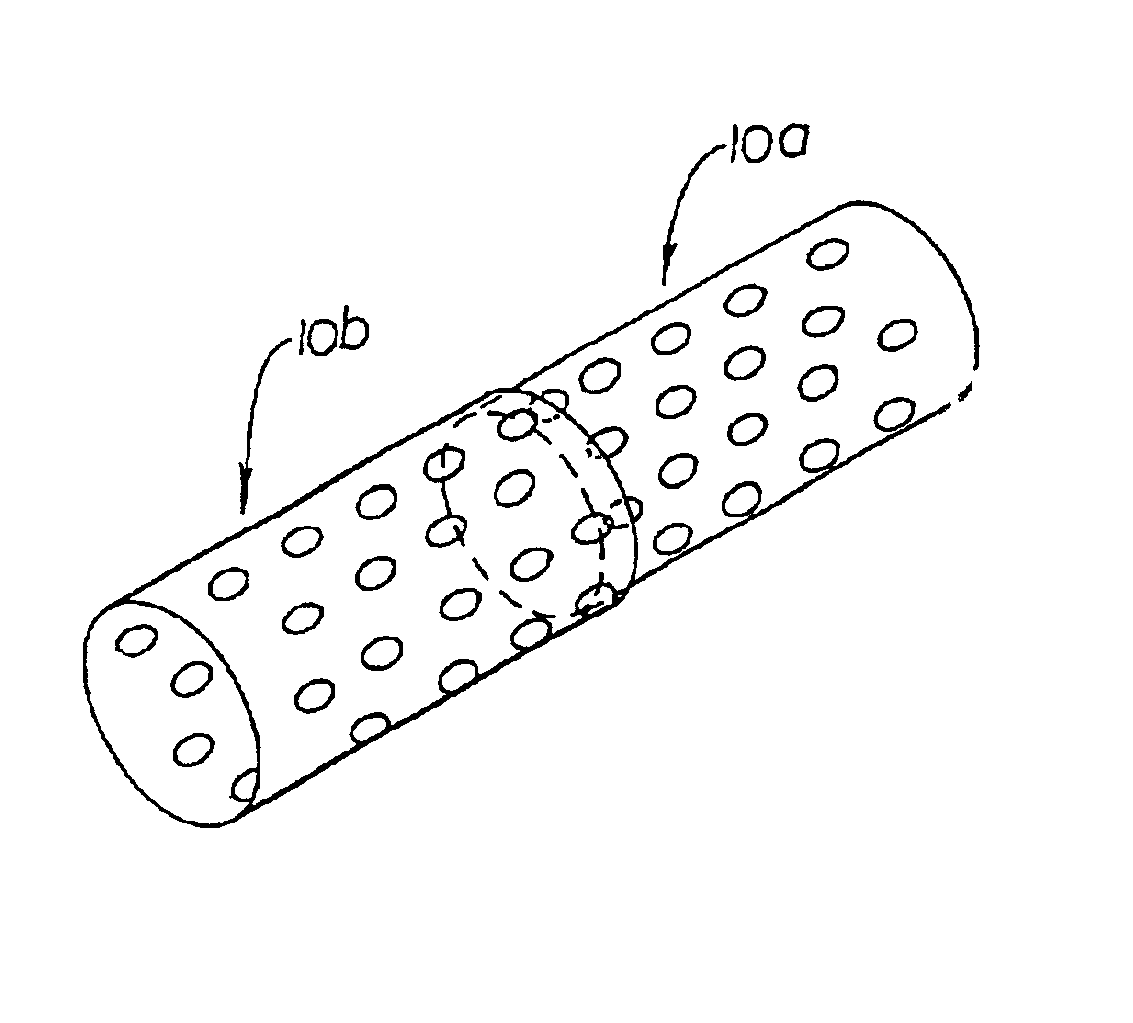
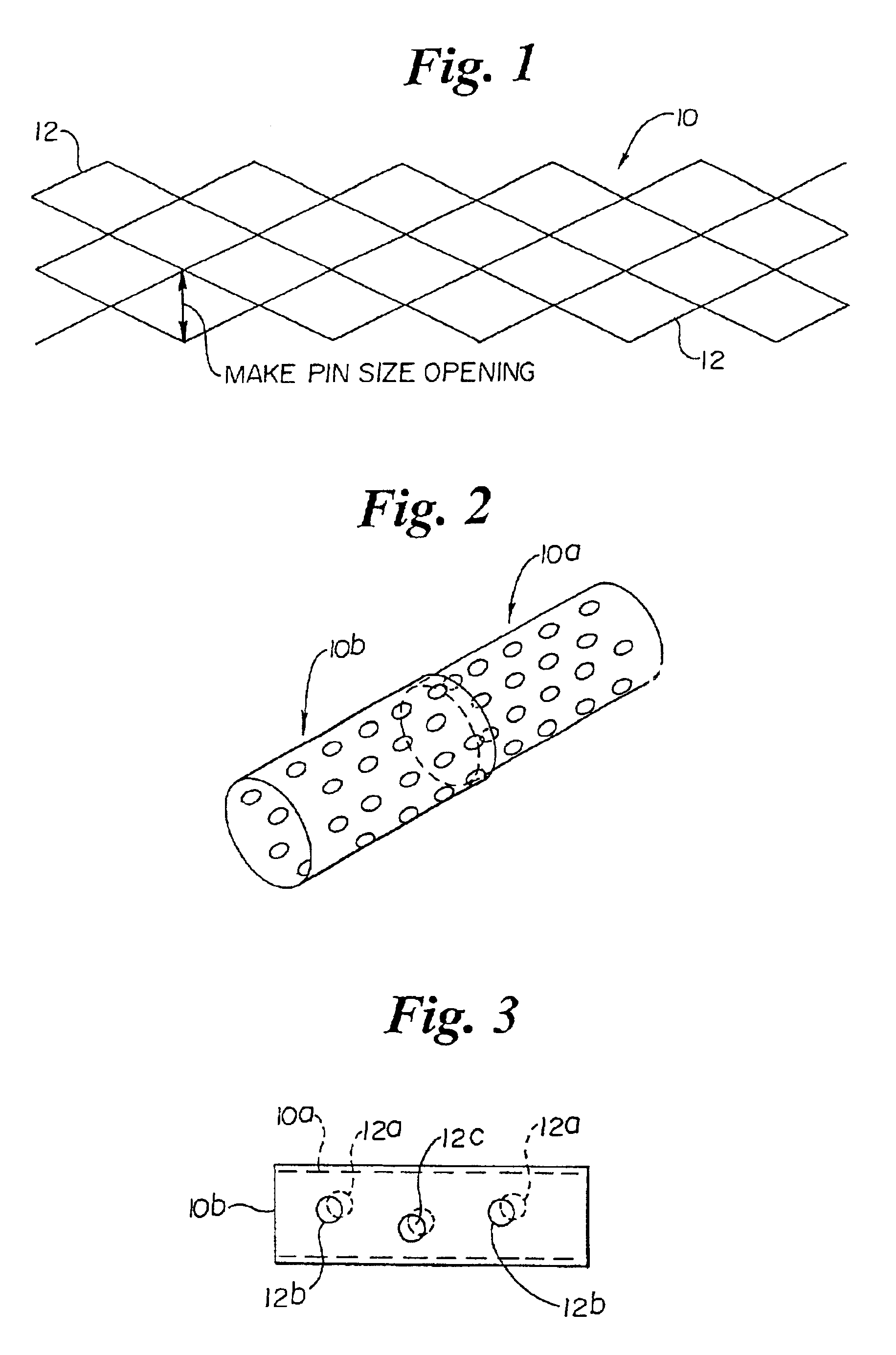
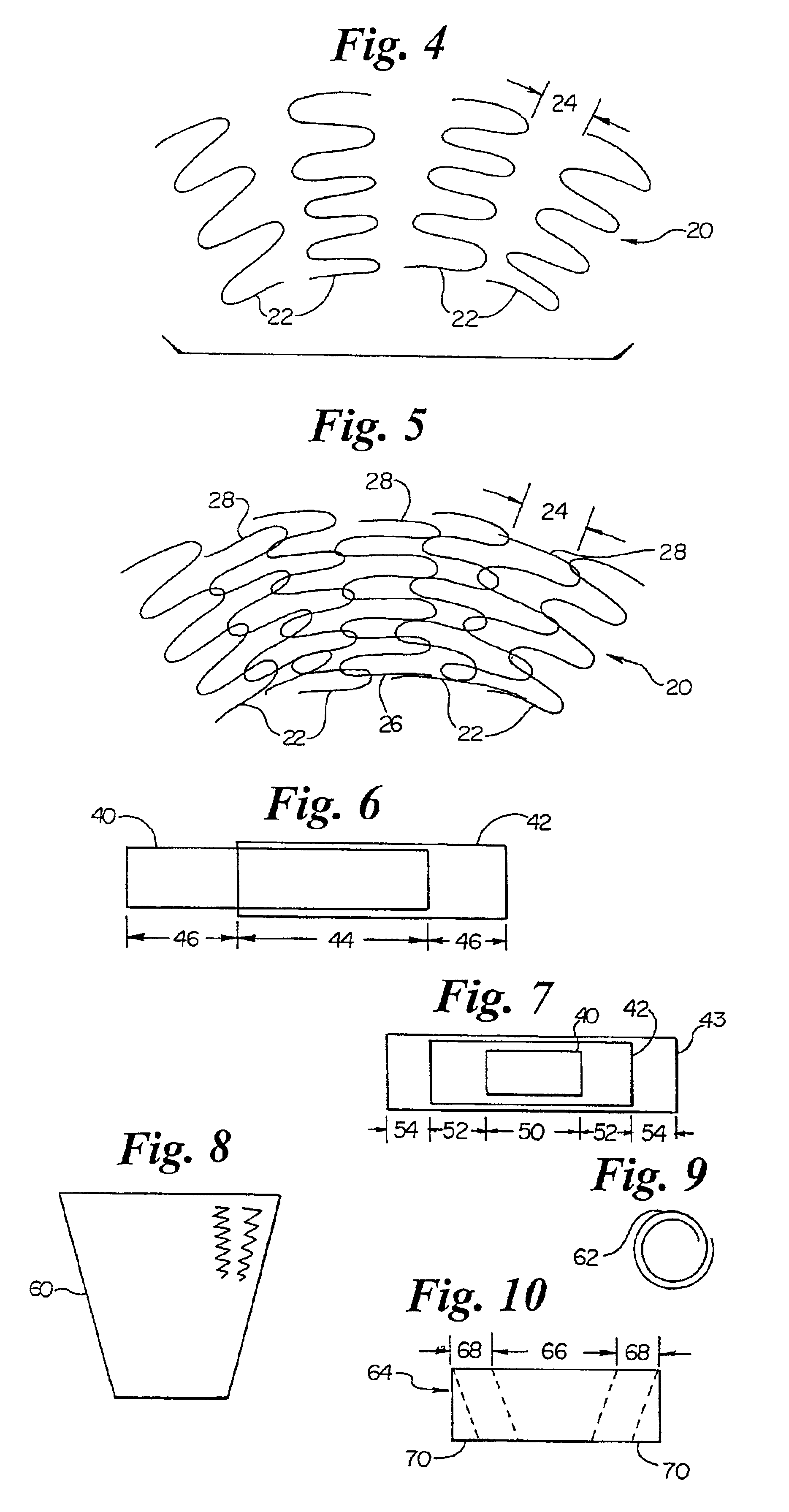
  • Micro structure stent configurations
  • Micro structure stent configurations
  • Micro structure stent configurations

Examples


Embodiment Construction

This invention in contrast to the prior art jelly roll structure suggests that micro porous stents should be provided which have a deformable structure. Generally, this is meant that the deformable struts of both self-expanding and mechanically-expandable stents already known in the art should be provided with micro porous structure. The fabrication of such stents is typically from flat sheet which is rolled then welded into a cylinder or from tubular stock.

A first way involves simply making the struts and the openings of the stent extremely small. Such a stent would be comprised of a plurality of interconnected deformable struts arranged with respect to each other to provide a micro structure which facilitates support with a minimal disruption in the vessel of a body, the micro structure being characterized, after expansion, by about the following dimensions or smaller.strut width 0.00025-0.002 inchesstrut thickness 0.00025-0.004 inchesmaximum PIN opening 0.002-0.20 inches

Having re...


PUM


Abstract

Fine structure stents physiologically acceptable to the body.

Description

BACKGROUND OF THE INVENTIONThis invention relates to medical stents. Medical stents are well know for use in opening and reinforcing the interior wall of blood vessels and other body conduits.Stents are generally tubular in configuration and radially expandable. They may be of the self-expanding type or they may be mechanically expandable with an outward pressure applied to the stent. Typically, the later type stents are expanded by means of an interiorly positioned balloon. Stents may be made of various materials such as plastic or metal. Presently, metal is the material of choice.This invention is specifically concerned with stents in the form of a closed cylinder which is made up of a plurality of struts, the struts being deformed either permanently or otherwise upon expansion of the stent.To-date, stents, particularly coronary stents, have been made up of elements that are relatively large and of the following order:strut width 0.004 inches 0.008 inchesstrut thickness 0.002 inch...

Claims


Application Information

Patent Timeline
IPC IPC(8): A61F2/06A61F2/00A61M31/00A61F2/90
CPCA61F2/915A61F2/91A61F2/852A61F2230/0013A61F2002/91533A61F2002/9155A61F2250/0018A61F2250/0023A61F2250/0029A61F2250/0036A61F2250/0039A61F2250/0063A61F2250/0067A61F2210/0076A61F2220/005A61F2220/0058
Inventor BROWN, BRIAN J.
Owner BOSTON SCI SCIMED INC
Learn More