Package for optical filter device

a technology of optical filter device and packaging, which is applied in the field of packaging for photonic devices, can solve the problems of time-consuming and expensive packaging, limited packaging approaches, and low cost of 3-port packages, and achieve the effects of minimizing stress levels, equal strength, and minimizing insertion losses

Inactive Publication Date: 2005-02-01
II VI DELAWARE INC
View PDF16 Cites 4 Cited by
  • Summary
  • Abstract
  • Description
  • Claims
  • Application Information

AI Technical Summary

Benefits of technology

In an embodiment involving a 3-port device, the dual-fiber ferrule pigtail positioned inside the glass holding tube is aligned and then adhesively bonded to the end face of the input collimating lens, while the single fiber-ferrule pigtail positioned inside the glass holding tube is aligned and then bonded to the end face of the output collimating lens. The simplified alignment operations include translational (lateral) iterative steps minimizing the insertion losses in the reflected and transmitted optical signals. The obtained optimum interrelationships between input, output and filtering-collimating assemblies are then adhesively secured. A heat or UV curable epoxy adhesive is used. Two butt joints formed are thin rings of adhesive that are also external to all optical paths of the package.
Structurally, the packaged system is a stepped cylindrical beam. Optimizing the structural dimensions of the supporting glass tubes, one can design a package of equal strength (resistance) in all cross-sections of the packages. This additionally minimizes the stress levels in structural and optical elements as well as in bond layers and therefore improves optical performance of the package due to possible mechanical and environmental excitations (loads).
The present invention provides a filtering-collimating optical assembly that may be fashioned in a manner that is fully passively aligned, with little or no need for active alignment. The present invention can provide an adhesively bonded optical assembly for two-port, three-port, and higher port-count temperature-compensated optical filtering packages used in dense wavelength-division multiplexing (DWDM) modules, or polarization-beam combiner-splitters and isolators. With this assembly, the role of active alignment in the manufacturing of various packages and modules can be minimized or even eliminated and replaced by semi-automated passive alignment. The optical sub-components may be designed to be coupled together in modular fashion to form an optical assembly that can be applicable to various networking devices.

Problems solved by technology

The filter price and the packaging costs are two dominating factors affecting the cost of the 3-port packages and WDM modules.
All this makes manufacturing of the packages time-consuming and expensive.
However, these packaging approaches still exhibit certain limitations.
In assembly, a previously achieved precise active alignment can be easily harmed due to heat-cure assisted polymerization and the accompanying it thermal shrinkage in a subsequent step.
Thus, in spite of the simplifications in the package design and manufacturing suggested in these references, the packaging process remains time-consuming and expensive.

Method used


Image

  • Package for optical filter device
  • Package for optical filter device
  • Package for optical filter device

Examples


Embodiment Construction

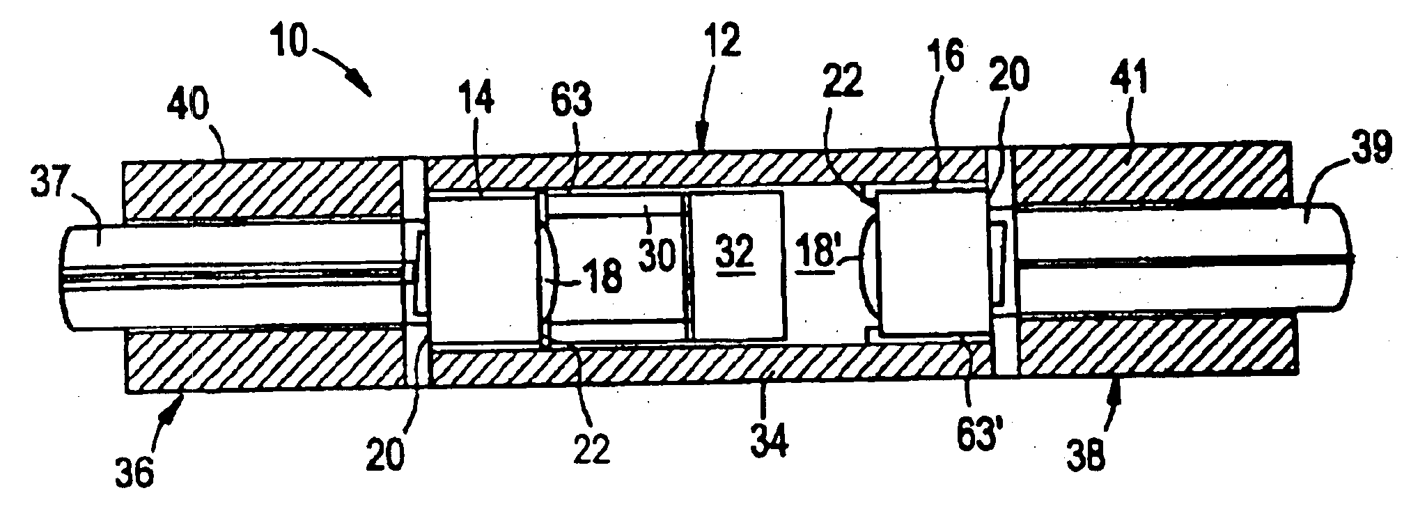
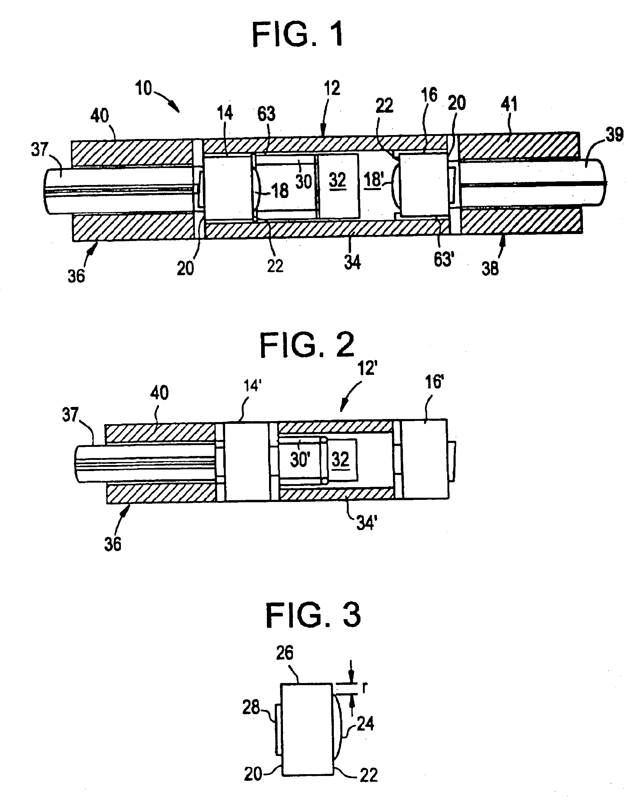
Reference will now be made in detail to the present preferred embodiments of the invention, examples of which are illustrated in the accompanying drawings. Whenever possible, the same reference numerals will be used throughout the drawings to refer to the same or like parts. One embodiment of the optical assembly of the present invention is shown in FIG. 1, and is designated generally throughout by the reference numeral 10.

As embodied herein and depicted in FIG. 1, an optical assembly such as the illustrated 3-port thin film filter package 10, includes a central unit 12 having a first lens 14 and a second lens 16 arranged on a common optical path, preferably with substantially coincident optical axes. Each of the lenses 14, 16 has a central transmission region with a convex aspheric segment 18, 18′ through which light passes from a first side to a second side of the lens, and a first 22 and a second 20 table ring region on the periphery of the transmission region. Suitable lenses ar...


PUM


Abstract

An optical assembly includes a lens unit having a first lens and a second lens arranged on a common optical path with substantially coincident optical axes. Each lens has a transmission region through which light passes from a first side to a second side of the lens, and a first and a second table region on the periphery of the transmission region. The table regions are flat surfaces positioned on the first and second sides of each lens. An optical element holding tube is butt-coupled to the first table region of the first lens. An optical element, such as a filter, is supported on the first element holding tube. A second lens support tube holds the first lens and the second lens at opposite ends, with the first element holding tube therebetween. The first and second lenses and the optical element are passively aligned and then fixed in place with optical adhesive at the butt joints.

Description

BACKGROUND OF THE INVENTION1. Field of the InventionThe present invention relates generally to packaging for photonic devices and particularly to packaging for 2-, 3- and multiple-port optical devices such as WDM filters, and various crystal-based devices.2. Technical BackgroundA typical WDM module includes numerous optical circuits arranged in parallel and in series to address a large number of channels. Each circuit is formed by a number of collimating and / or filtering-collimating assemblies, each including a 3-port filtering package that includes optical fibers inserted and bonded into glass ferrules to produce fiber-ferrule “pigtails,” collimating lenses, and a spectral shaping thin film optical filter. In a typical 3-port package, the collimating lens receives the light emitted from the input fiber, collimates this light into parallel rays, and transmits them to the filter. The filter splits the collimated light into two separate beams, a transmitted beam and a reflected beam. ...

Claims


Application Information

Patent Timeline
Patent Type & Authority Patents(United States)
IPC IPC(8): G02B6/32G02B6/34G02B6/38
CPCG02B6/2937G02B6/32G02B6/3845
Inventor HELLMAN, SCOTT M.TOWNLEY-SMITH, PAUL A.USHINSKY, MICHAEL
Owner II VI DELAWARE INC
Why Eureka
Try Eureka