System and method for high-capacity electronic switching

a high-capacity electronic switching and electronic switching technology, applied in data switching networks, frequency-division multiplexes, instruments, etc., can solve the problems of large circuit scale, difficult to realize the establishment of necessary communication links appropriately, and high-speed operation of tdm switches

Inactive Publication Date: 2005-02-01
NEC INFRONTIA CORP
View PDF26 Cites 4 Cited by
  • Summary
  • Abstract
  • Description
  • Claims
  • Application Information

AI Technical Summary

Benefits of technology

It is therefore the primary object of the present invention to provide a high-capacity electronic switching system, in which communication link setting between the subscriber terminals can be executed even when the communication link setting via an upper stage switch module (the second stage switch module etc.) is impossible.

Problems solved by technology

Such an electronic switching system employing a TDM switch is required high speed operation and large circuit scale if the number of the subscriber circuits becomes large.
However, it is difficult to realize establishment of necessary communication links appropriately by means of one TDM switch, when the number of the subscriber circuits increases.
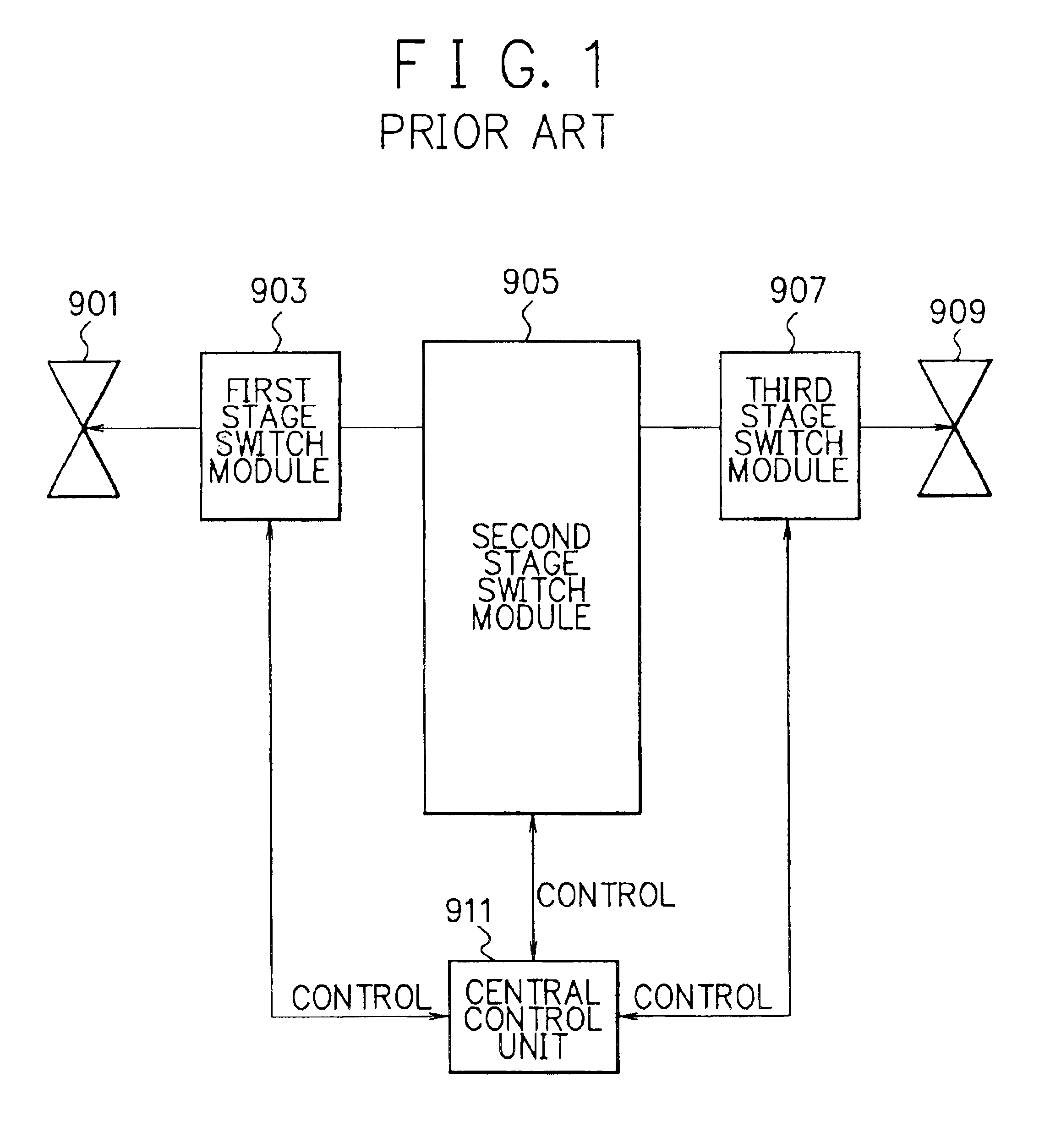
However, in the first conventional high-capacity electronic switching system, control of the switch modules becomes impossible when failure occurred in the central control unit 911, and thereby the setting of the communication link between subscriber terminals becomes impossible.
Therefore, the first conventional high-capacity electronic switching system lacks resistance to abnormality such as failure in the central control unit 911.
Therefore, if an abnormal condition occurred in the second stage switch module 700 and the second stage switch module 700 can not execute signal switching normally, the communication link setting between the two subscriber terminals becomes impossible.
However, if the two subscriber terminals are connected to different first / third stage switch modules, signal switching and data communication between the two subscriber terminals become impossible.

Method used


Image

  • System and method for high-capacity electronic switching
  • System and method for high-capacity electronic switching
  • System and method for high-capacity electronic switching

Examples


first embodiment

FIG. 4 is a schematic block diagram showing a high-capacity electronic switching system according to the present invention. The high-capacity electronic switching system shown in FIG. 4 employs alternative communication links for the TDM communication links.

Referring to FIG. 4, the high-capacity electronic switching system of the first embodiment employs 3-stage connection of switches similarly to the prior art. The high-capacity electronic switching system is mainly composed of a second stage switch module 200, n+1 (n: integer larger than 0) first / third stage switch modules 100, 101, . . . , 10n, and a special-purpose link 500.

The first / third stage switch module 100 includes a subscriber circuit 130, a special-purpose link interface 140, a TDM (Time Division Multiplexing) switch 110 and a central control unit 120 for controlling the subscriber circuit 130, the special-purpose link interface 140 and the TDM switch 110. Similarly, each first / third stage switch module (101, 102, . . ....


PUM


Abstract

A high-capacity electronic switching system includes two or more first stage switch modules to each of which one or more subscriber terminals (telephone sets, fax machines, personal computers, etc.) are connected and each of which executes signal switching for signals from/to the subscriber terminals, and a second stage switch module for switching signals between the first stage switch modules. In the high-capacity electronic switching system, each of the first stage switch modules is connected to another one of the first stage switch modules via a special-purpose link for setting a communication link between the first stage switch modules when necessary. For example, the setting of the communication link via the special-purpose link is executed when an abnormal condition of the second stage switch module occurred and normal communication link setting between two first stage switch modules via the second stage switch module is impossible. By this, even when failure occurred to the second stage switch module and communication between two first stage switch modules is impossible, a communication link can be set between the first stage switch modules via the special-purpose link, and thereby communication between the first stage switch modules is realized.

Description

BACKGROUND OF THE INVENTIONThe present invention relates to a high-capacity electronic switching system and a high-capacity electronic switching method, and in particular, to a high-capacity electronic switching system and a high-capacity electronic switching method by which resistance to abnormal conditions is improved and thereby communication links can be set between subscriber terminals even in such abnormal conditions.DESCRIPTION OF THE PRIOR ARTElectronic switching systems are widely used today in large-scale networks such as telephone networks, in order to switch and exchange information transmitted from terminals such as telephone sets, facsimile machines, servers, etc. For example, EPBXs (Electronic Private Branch Exchanges) are employed in buildings etc. as the electronic switching systems.The electronic switching system is generally provided with subscriber circuits as the interface between the network and subscriber terminals (such as telephone sets, facsimile machines, ...

Claims


Application Information

Patent Timeline
Patent Type & Authority Patents(United States)
IPC IPC(8): H04Q3/58H04Q3/64H04Q3/68H04M3/00H04Q11/04H04Q3/545
CPCH04Q3/58H04Q3/68H04Q2213/1322H04Q2213/13176H04Q2213/13166
Inventor KAKIUCHI, MOTOFUMI
Owner NEC INFRONTIA CORP
Why Eureka
Try Eureka