2-D microscopic tomographic systems utilizing 2-D deflection sensors

a tomographic system and sensor technology, applied in the field of microscopy and tomography, can solve the problems of reducing the data acquisition time, consuming the process of acquiring data pixel by pixel, and not being able to apply ultra high-resolution microscopes such as atomic force microscopes

Inactive Publication Date: 2005-02-01
KHOURY JED
View PDF1 Cites 17 Cited by
  • Summary
  • Abstract
  • Description
  • Claims
  • Application Information

AI Technical Summary

Benefits of technology

FIG. 7: Fourier optics based high-pass filtering scheme.

Problems solved by technology

This made acquiring the data on a pixel by pixel basis a time consuming process.
For many industrial applications this can be very costly.
Others utilized the possibility of focusing an array of diode lasers into the sample; Even though there was a significant reduction in the data acquisition time, these approaches were not applicable with ultra high-resolution microscopes such as atomic force microscopes; see H. Kumar Wickramasinghe.

Method used


Image

  • 2-D microscopic tomographic systems utilizing 2-D deflection sensors
  • 2-D microscopic tomographic systems utilizing 2-D deflection sensors
  • 2-D microscopic tomographic systems utilizing 2-D deflection sensors

Examples


Embodiment Construction

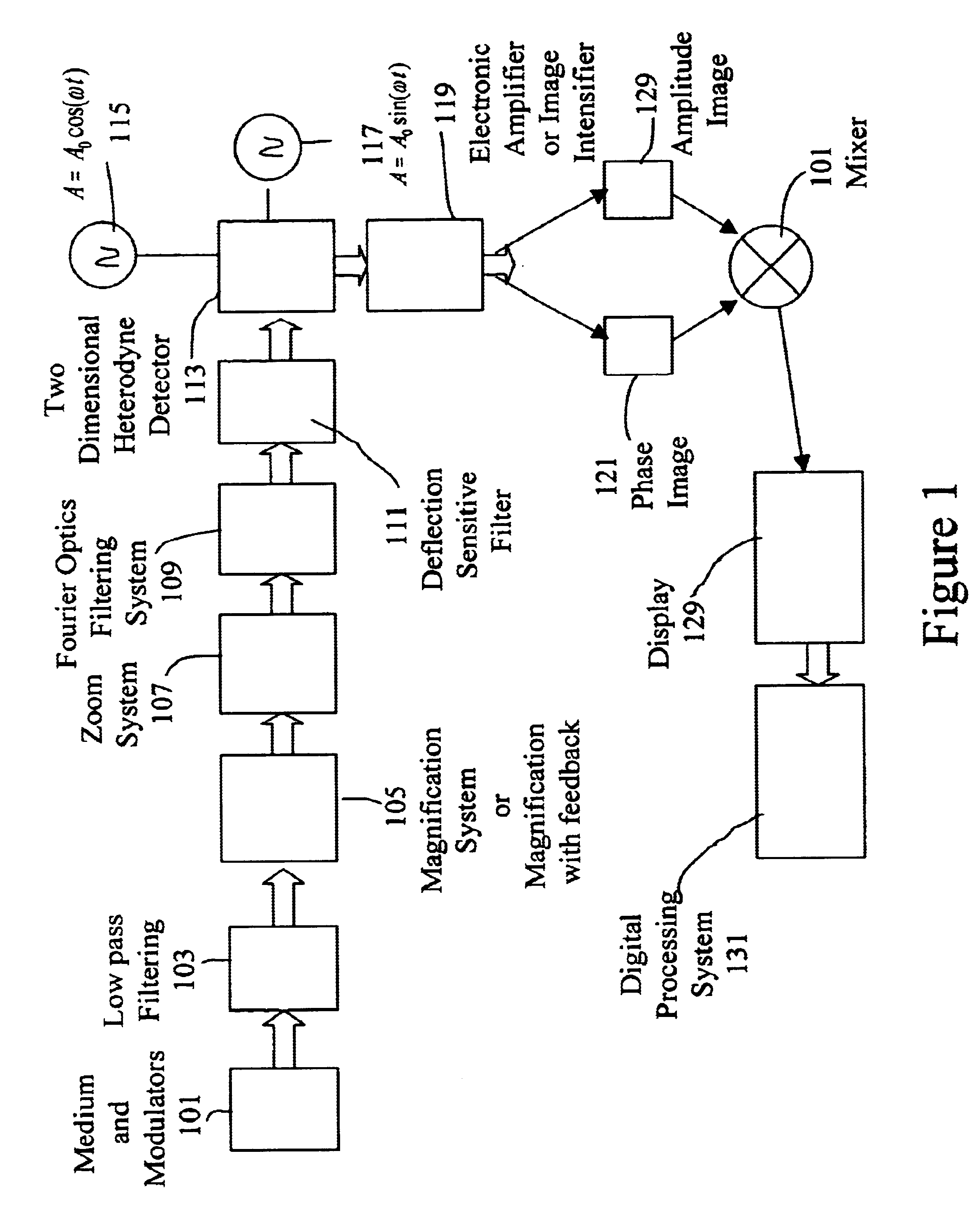
A high pass optical filter having a Fourier transform lens coupled to a DC blocking member, receives the output of a modulator for modulating an input image introduced into the system, and for applying a broad, non-focused modulated signal image to the high pass filter.

A zoom lens is provided to enable viewing of selected slices of a three dimensional object image such as a tumor. An image magnification device having a feedback loop is coupled between the high pass optical filter and the zoom lens and a deflection sensitive filter. The deflection sensitive filter is optionally provided for encoding a phase map for certain applications of tomography. A Fourier optics filter is coupled between the zoom lens and the deflection sensitive filter addressed via the back propagation algorithm for distortion compensation.

A two dimensional demultiplexer receives output signals from the deflection sensitive filter, and a calculating device is coupled to the demultiplexer for calculating separa...


PUM


Abstract

A high resolution, non-scanning system for microscopy and/or tomography whereby a broad non-focused input image transmitted through a medium such the human body is processed, in contrast with a focused scanning beam. A high pass filter provides high sensitivity, and a high magnification feedback loop magnifier having reduced lens aberrations is also provided. A zoom lens focuses the input image such as a tumor at different planes within the medium. Image processing systems for correction via a back-propagation algorithms followed by a two-dimensional (2-D) deflection sensor and a 2-D Demultiplexer is employed to produce separate phase and amplitude image signals that are then mixed and applied to a display yielding three dimensional tomographic images. Novel two demultiplexers for calculation amplitude and phase images are disclosed based on a smart pixelated array, a tunable grating, and a two-probe beam hologram, each beam having two different wavelengths or two different modulations.

Description

BACKGROUND OF THE INVENTIONFor several decades microscopy and tomography were designed using scanning approaches; see Theodore George Rochow and Eugene George Rochow, “An introduction to microscopy by, means of light, electron, X ray, or ulrasound” Plenum Press, 1978. This made acquiring the data on a pixel by pixel basis a time consuming process. For many industrial applications this can be very costly.The general feature which unifies all microcopies and tomographies, is a modulated or pulsed focussed pencil probe beam that is detected and sent to deflection sensor then demultiplexer (time, heterodyne) to extract the required information for building the image See Kyuman Cho, David L. Mazzoni and Christopher C. Davis, “measurement of local slope of a surface by vibrating-sample heterodyne interferometry: A new method for scanning microscopy. Optics Letters, Vol. 18 Issue 3 Page 232, T. Sawatari Optical heterodyne scanning microscope. Appl. Opt. 12, 2768-2772 (1973).A significant p...

Claims


Application Information

Patent Timeline
Patent Type & Authority Patents(United States)
IPC IPC(8): G06T5/50G21K7/00
CPCG06T5/50G02B21/0004
Inventor KHOURY, JED
Owner KHOURY JED
Why Eureka
Try Eureka