Household food warmer for keeping foods and beverages warm

Inactive Publication Date: 2005-02-01
MIELE & CO KG
View PDF14 Cites 42 Cited by
  • Summary
  • Abstract
  • Description
  • Claims
  • Application Information

AI Technical Summary

Benefits of technology

Thus, it is an object of the present invention to provide a household food warmer and a method for keeping foods and beverages warm in a household food warmer, in which quick heating to a desired interior chamber temperature is achieved with reduced thermal loading of the surface of the foods and beverages placed in the interior chamber.
In addition to quick heating to a desired interior chamber temperature with reduced thermal loading of the surface of the foods and beverages placed in the interior chamber, an advantage that can be achieved with the present invention is a more uniform initial heating because the air heated by the heating element is distributed in the interior chamber by the convection fan. Thus, for example, in spite of quick heating to the desired interior chamber temperatures, the food is substantially prevented from drying out, thus maintaining the taste and appearance of the food that is placed in the interior chamber to be kept warm. This is true in particular for higher keep-warm temperatures, which, in the known household food warmer, require either a higher initial heating power of the heating element, or a longer initial heat-up time. Since the convection fan is only switched on for the relatively short initial heat-up time, the convection fan has a long service life.
In an embodiment of the present invention, the foods and beverages can be placed on the top side of a drawer bottom, and that the heating element and / or the convention fan is / are located in a region of the housing facing the top side of the drawer bottom. This promotes the transfer of heat from the heating element to the foods and beverages, resulting in shorter heat-up time and reduced energy requirement.
In another embodiment of the present invention, provision is made for the electrical circuit to be designed as an integrated electronic circuit. In this manner, it is possible to further reduce the space requirement. The space thus gained can be used for additional components, or for more powerful and therefore larger components, such as a more powerful convection fan.
In yet another embodiment, it is proposed that a bridging device having a manually operable bridging switch is arranged in the electrical circuit, it being possible for the convection fan to be switched on when the bridging switch is in a closed position, independently of the switching condition of the temperature sensor. This allows the household food warmer according to the present invention to be operated also in a plate warming mode, in which the convection fan is switched on for the whole keep-warm time, thus ensuring a particularly good transfer of heat between the heating element and the plates.

Problems solved by technology

Since the convection fan is only switched on for the relatively short initial heat-up time, the convection fan has a long service life.

Method used


Image

  • Household food warmer for keeping foods and beverages warm
  • Household food warmer for keeping foods and beverages warm
  • Household food warmer for keeping foods and beverages warm

Examples


first embodiment

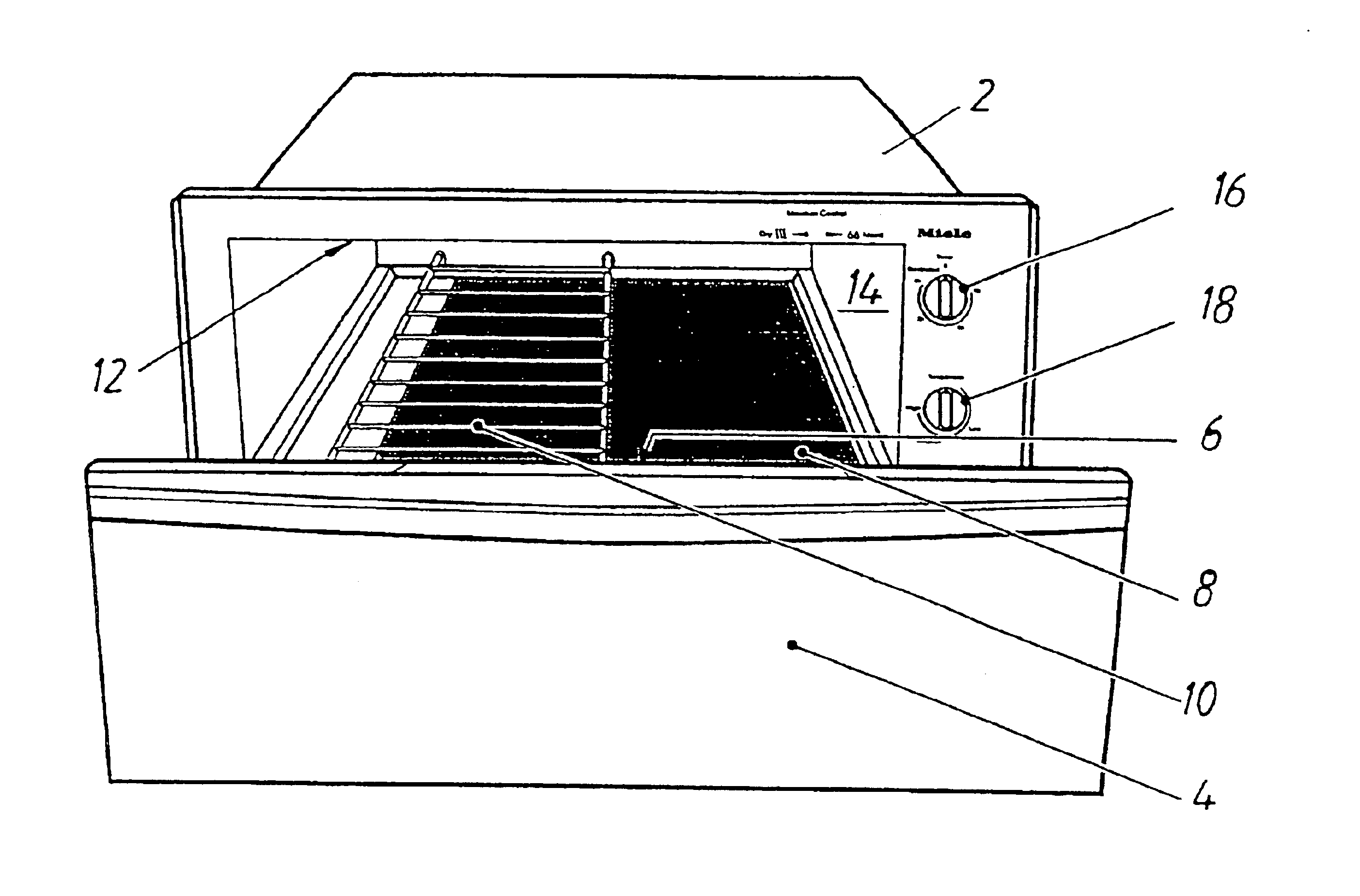
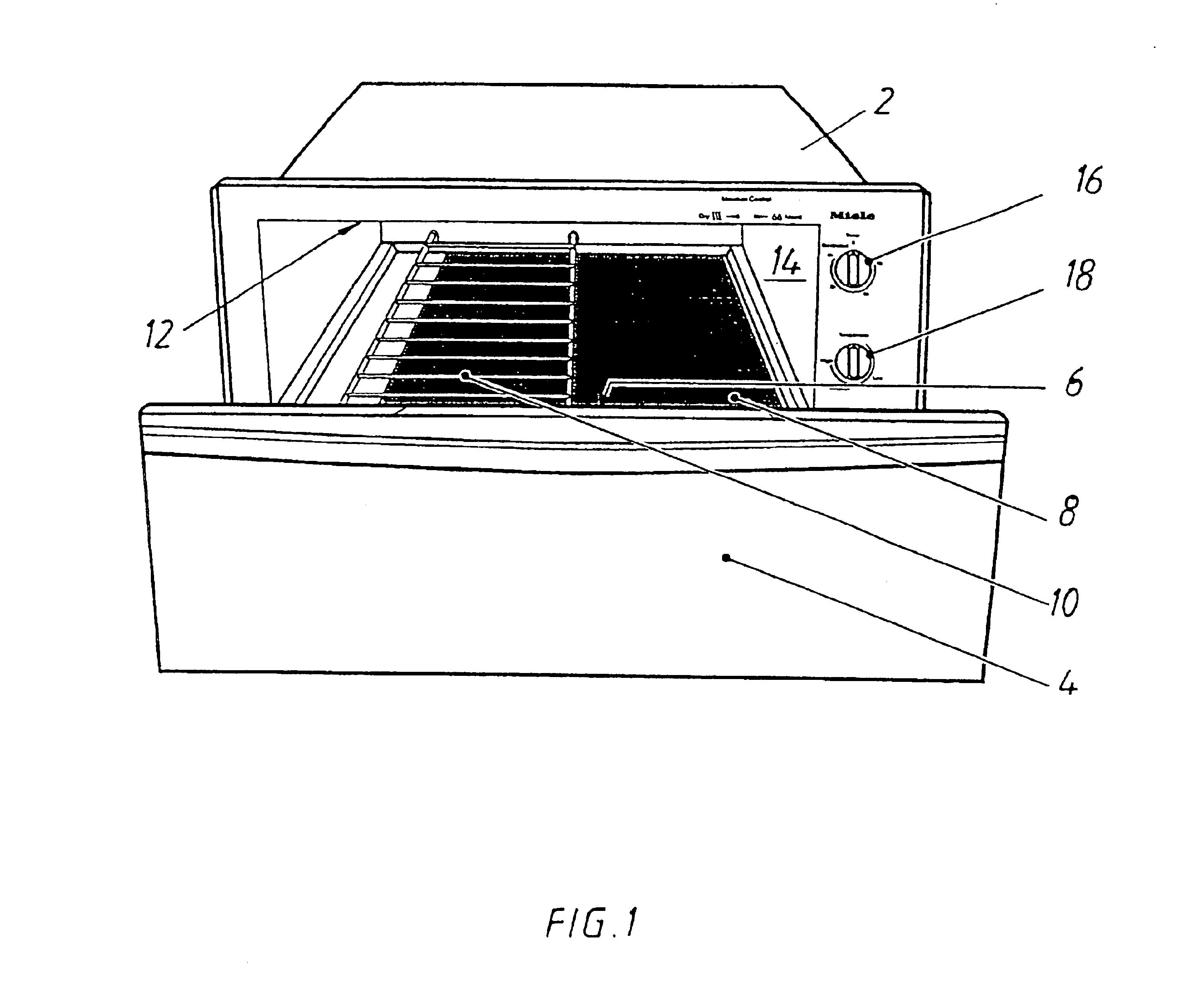
FIG. 1 shows a household food warmer according to the present invention for keeping foods and beverages warm. The household food warmer has a housing 2, and a drawer 4 which can be inserted into and held on housing 2. In FIG. 1, drawer 4 is only partially inserted into housing 2. In the closed position of drawer 4, that is, when drawer 4 is fully inserted, an interior chamber 6 is bounded by housing 2 and drawer 4. Interior chamber 6 is designed to accommodate foods placed on plates and beverages filled in drinking vessels. In this embodiment, the plates and drinking vessels can be placed on top side 8 of a drawer bottom. Alternatively or additionally, a rack 10, on which plates and drinking vessels may be placed, can be arranged in interior chamber 6. A heating element, which is designed as an electric radiant heating element, is located at ceiling 12 of interior chamber 6, which is formed on housing 2 and faces top side 8; the heating element being capable of being switched on and...

second embodiment

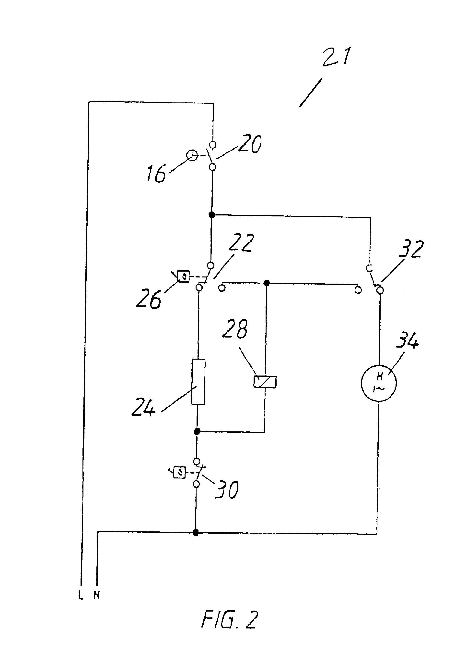
The mode of operation of the second embodiment will now be explained in more detail with reference to FIG. 3.

The household food warmer according to the present invention has been set into operation as described above. As long as the user does not operate electrical bridging switch 38 after setting the household food warmer according to the present invention into operation, the mode of operation is the same as that already explained with reference to the first embodiment. If electrical bridging switch 38 is now manually closed, further relay 36 is connected to the electrical network, and automatically moves further changeover switch 42 from its normal position to its displaced position so that relay 28 is disconnected from the electrical network independently of the position of first electrical switch 22. Consequently, second electrical switch 32 remains in its normal position, and the convection fan remains electrically conductively connected to the electrical network for the whole ...


PUM


Abstract

A household food warmer for keeping foods and beverages warm includes a housing, a drawer which can be inserted into the housing, an interior chamber which is bounded by the housing and the inserted drawer and which is used to accommodate foods placed on plates, a heating element, an electrical circuit in which is arranged a first electrical switch for switching on the heating element, and a temperature sensor for measuring the interior chamber temperature. A convection fan is provided. The convection fan can be switched on via a second electrical switch arranged in the electrical circuit and can be switched off via the second electrical switch upon the occurrence of a switching condition that is dependent on the temperature sensor.

Description

Priority is claimed to German patent application DE 102 60 019.8, which is hereby incorporated by reference herein.The present invention relates in general to household food warmers, and particularly to a household food warmer having a convection fan.BACKGROUNDHousehold food warmers for keeping foods and beverages warm are generally known and offered by different manufacturers. For example, the Dacor Company of Pasadena, USA, distributes such a household food warmer under the name “EDWO30S”. The known household food warmer includes a housing, a drawer which can be inserted into the housing, and has an interior chamber which is bounded by the housing and the inserted drawer, and which is used to accommodate the foods placed on plates. The plates are placed on the top side of a drawer bottom. To heat the interior chamber, the known household food warmer is further equipped with a heating element, which is located at the inner housing wall facing the top side of the drawer bottom, an e...

Claims


Application Information

Patent Timeline
IPC IPC(8): F24C15/18F24C15/00F24C7/08
CPCF24C15/18F24C7/087
Inventor BOLLMERS, WOLFGANGEMPTING, MICHAELRENNE, JOHANNESSTEMIG, PETERWEMHOENER, HARTMUT
Owner MIELE & CO KG
Why Eureka
Try Eureka