
Color filter and process for producing the same

a color filter and process technology, applied in the field of color filters, can solve the problems of high cost, high cost, and high demand for the cost-cutting of color filters in a respect of cost, and achieve the effects of low cost, easy handling, and increasing reaction ra

Inactive Publication Date: 2005-02-01
DAI NIPPON PRINTING CO LTD
View PDF3 Cites 7 Cited by
  • Summary
  • Abstract
  • Description
  • Claims
  • Application Information

AI Technical Summary

Benefits of technology

The present invention provides a color filter with a wettability-variable layer that can form a picture element part with better precision and no color nonuniformity. The wettability-variable layer can vary its wettability to form the picture element part and the shading part. The color filter can be made with the use of an inkjet system and has improved quality with no color mixing or color nonuniformity. The wettability-variable layer can be formed on the border part of the picture element part or on the shading part. The invention also provides a method for making the color filter with the wettability-variable layer.

Problems solved by technology

However, since this color liquid crystal display is expensive, a demand for the cost-cut is getting higher and, in particular, a demand for the cost-cut of a color filter weighing in a respect of cost is high.
However, in any method, the same step needs to be repeated three times for coloring three colors of R, G and B, and there is a problem that the cost is high and a yield is decreased because of repetition of a step.
However, there is no description regarding how to specifically coat a material having the better wettability and a material having the worse wettability.
However, in this method, since a convex part needs to be ink-repellent in advance upon the inkphilic treatment, there is a problem that two times treatments of the ink-repulsion treatment and the inkphilic treatment need to be performed.
However, in this method, since a colored layer is formed by forming an absorbing layer and absorbing an ink in this absorbing layer, there is a problem that a difference in the coloration between a central part of an ink dot and a surrounding part of that is present which results in the color nonuniformity.
In addition, there is also a problem that this absorbing layer needs the predetermined thickness resulted from its function of absorbing an ink.

Method used


Image

  • Color filter and process for producing the same
  • Color filter and process for producing the same
  • Color filter and process for producing the same

Examples


first embodiment

1. The First Embodiment

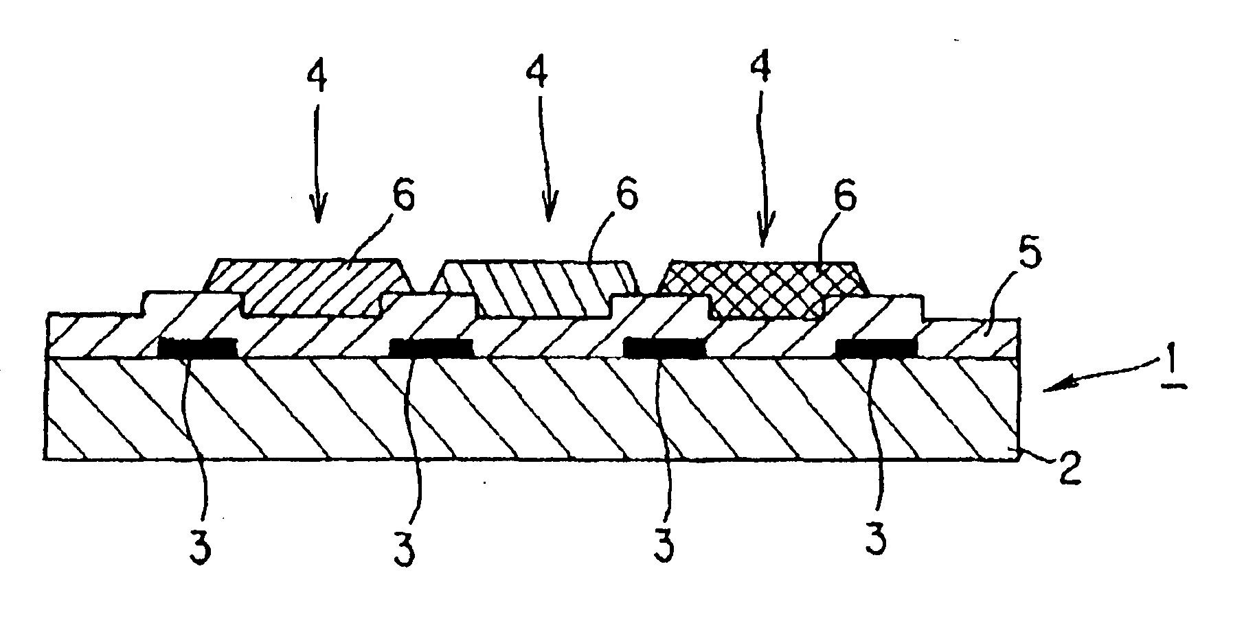
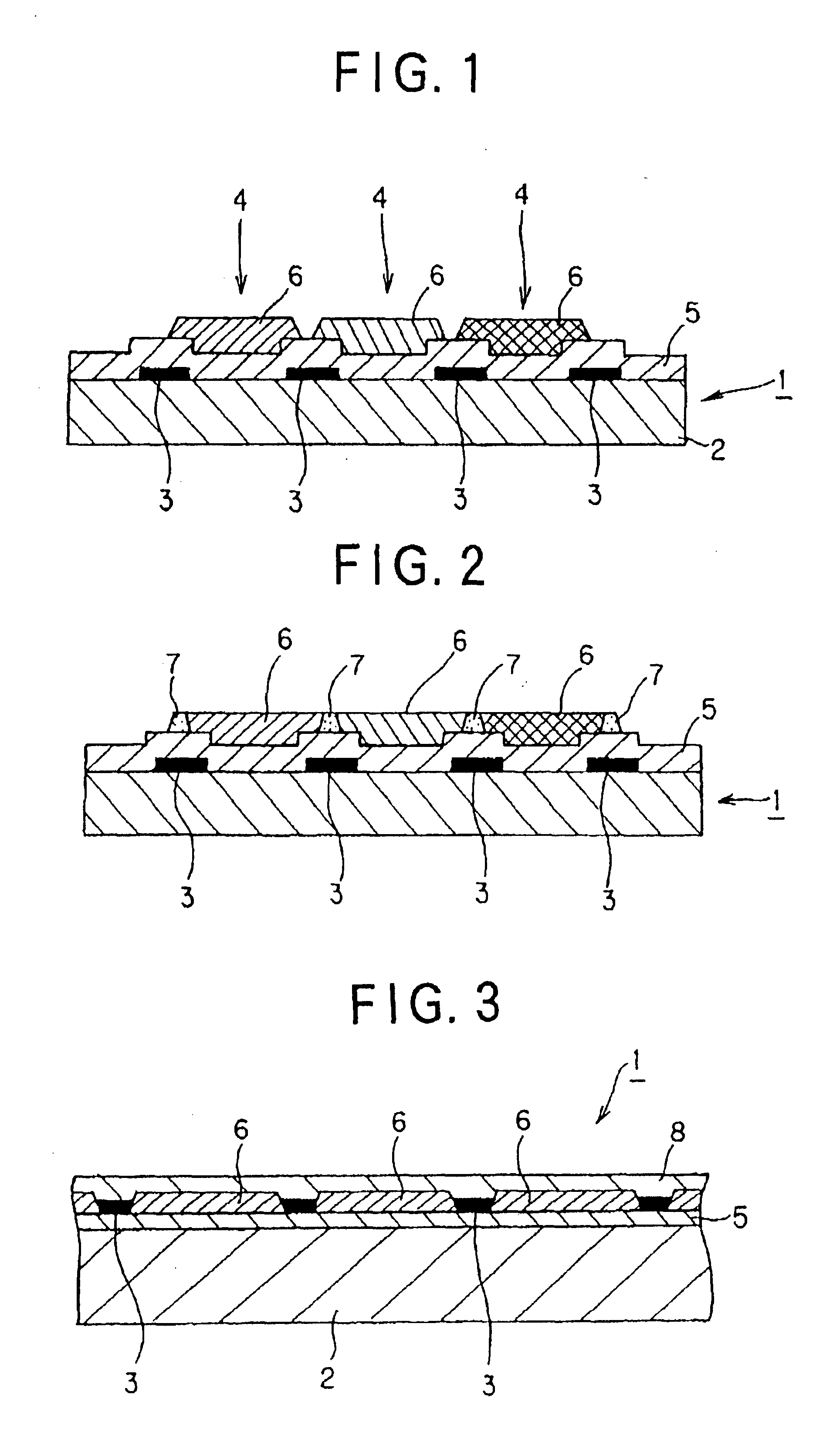
The first embodiment of the present invention is a color filter in which a shading part is formed on a transparent substrate, a wettability-variable layer is provided on a picture element part forming portion which is a part on at least this shading part and on the transparent substrate on which the picture element part is to be formed, and further a picture element part can be formed with the better precision by varying the wettability on this wettability-variable layer. This shows an example in which a wettability-variable layer is provided for forming a picture element part and is one of specific examples of a color filter in which the aforementioned at least a picture element part is provided on a wettability-variable layer.

FIG. 1 shows one example of the first embodiment. This color filter 1 has a shading part 3 provided on a transparent substrate 2, a wettability-variable layer 5 provided on a picture element part forming portion 4 which is a part on the...

second embodiment

2. The Second Embodiment

The second embodiment of the present invention is a color filter in which a wettability-variable layer is formed on the whole a surface of a transparent substrate and a picture element part and a shading part are provided at the predetermined position on this wettability-variable layer. This indicates an example in which a wettability-variable layer is provided for forming a picture element part and a shading part and one specified example of the aforementioned color filter in which at least a picture element part is provided on a wettability-variable layer.

FIG. 3 shows an example of the second embodiment. This color filter 1 is formed of a wettability-variable layer 5 provided on a transparent substrate 2, a shading part 3 and a picture element part 6 formed on this wettability-variable layer 5 and a protecting layer 8 provided on this picture element part 6 and shading part 3.

In this color filter of the second embodiment, a picture element part 6 and a shad...

third embodiment

3. The Third Embodiment

The third embodiment of the present invention is a color filter in which the aforementioned shading part is provided on a transparent substrate, a wettability-variable layer is provided on a picture element part forming portion on the transparent substrate, which is a part on which a picture element part is to be formed, and a picture element part is provided on this wettability-variable layer. This shows an example in which a wettability-variable layer is provided for forming a picture element part and a shading part and, as described above, is one specified examples of a color filter in which at least a picture element part is provided on a wettability-variable layer.

FIG. 4 shows one example of the third embodiment. This color filter 1 is formed of a shading part 3 provided on a transparent substrate 2, a wettability-variable layer 5 formed in a pattern like state on a picture element part forming portion 4 which is a region between the aforementioned shadin...


PUM

PropertyMeasurementUnit
surface tensionaaaaaaaaaa
contact angleaaaaaaaaaa
surface tensionaaaaaaaaaa

Abstract

There is provided a color filter which comprises a transparent substrate, a picture element part provided on the transparent substrate by the predetermined pattern of a plurality of colors with an ink jet system, a shading part provided on a border part of this picture element part, and a wettability-variable layer, in which the wettability can be changed, provided for forming the picture element part or the picture element part and the shading part.

Description

PRIORITYIt is noted that certified copies of the Japanese priority application were submitted on Mar. 20, 2000 in applicant's parent application, Ser. No. 09 / 453,063.BACKGROUND OF THE INVENTIONThe present invention relates to a color filter which is obtained by coloring a picture element part with an ink jet system and which is suitable for a color liquid crystal display and a process for producing the same.Recently, there has been a tendency that a demand for a liquid crystal display, particularly a color liquid crystal display is increasing with the development of a personal computer, particularly a portable personal computer. However, since this color liquid crystal display is expensive, a demand for the cost-cut is getting higher and, in particular, a demand for the cost-cut of a color filter weighing in a respect of cost is high.In such a color filter, a liquid crystal usually operates as a shutter by equipping with three primary colors of red (R), green (G) and blue (B) and sw...

Claims


Application Information

Patent Timeline
Patent Type & Authority Patents(United States)
IPC IPC(8): B41J2/01G02B5/22G02B5/20G03F7/00G02F1/1335G02F1/13G03F7/004G03F7/075
CPCB41J2/01B82Y10/00B82Y40/00G02B5/201G03F7/0757G03F7/0007G03F7/0043G02B5/223B41J2202/09G02F1/133512G02F1/133516G03F7/0002
Inventor OKABE, MASATOKOBAYASHI, HIRONORIYAMAMOTO, MANABU
Owner DAI NIPPON PRINTING CO LTD
Learn More