
System for diagnosing operation of an EGR cooler

a technology for egr coolers and diagnostic systems, which is applied in the direction of machines/engines, mechanical equipment, and non-fuel substance addition to fuel, etc., can solve the problems of unfavorable egr system goals and formation of unwanted emissions

Inactive Publication Date: 2005-02-01
CUMMINS INC
View PDF39 Cites 94 Cited by
  • Summary
  • Abstract
  • Description
  • Claims
  • Application Information

AI Technical Summary

Benefits of technology

The present invention may comprise one or more of the following features and combinations thereof. A system for diagnosing operation of an exhaust gas recirculation (EGR) cooler may comprise an engine having an intake manifold, an exhaust manifold and an EGR conduit fluidly coupled between the intake and exhaust manifolds, wherein the engine further includes a cooling system having a coolant fluid circulating therethrough to cool the engine. An EGR cooler is disposed in-line with the EGR conduit such that exhaust gas flowing through the EGR conduit also flows through the EGR cooler, and the EGR cooler is operatively coupled to th...

Problems solved by technology

When combustion occurs in an environment with excess oxygen, peak combustion temperatures increase which leads to the formation of unwanted emissions, such as oxides of nitrogen (NOx).
This problem is aggravated through the use of turbocharger machinery operable to increase the mass of fresh air flow, and hence increase the concentrations of oxygen and nitrogen present in the combustion chamber when temperatures are high during or after the combustion event.
It is known that recirculation of exhaust gas into the fresh air stream generally increases the temperature of air charge entering the intake manifold, which under some engine operating conditions can frustrate the goals of an EGR system.

Method used


Image

  • System for diagnosing operation of an EGR cooler
  • System for diagnosing operation of an EGR cooler
  • System for diagnosing operation of an EGR cooler

Examples


Embodiment Construction

For the purposes of promoting an understanding of the principles of the invention, reference will now be made to a number of preferred embodiments illustrated in the drawings and specific language will be used to describe the same. It will nevertheless be understood that no limitation of the scope of the invention is thereby intended.

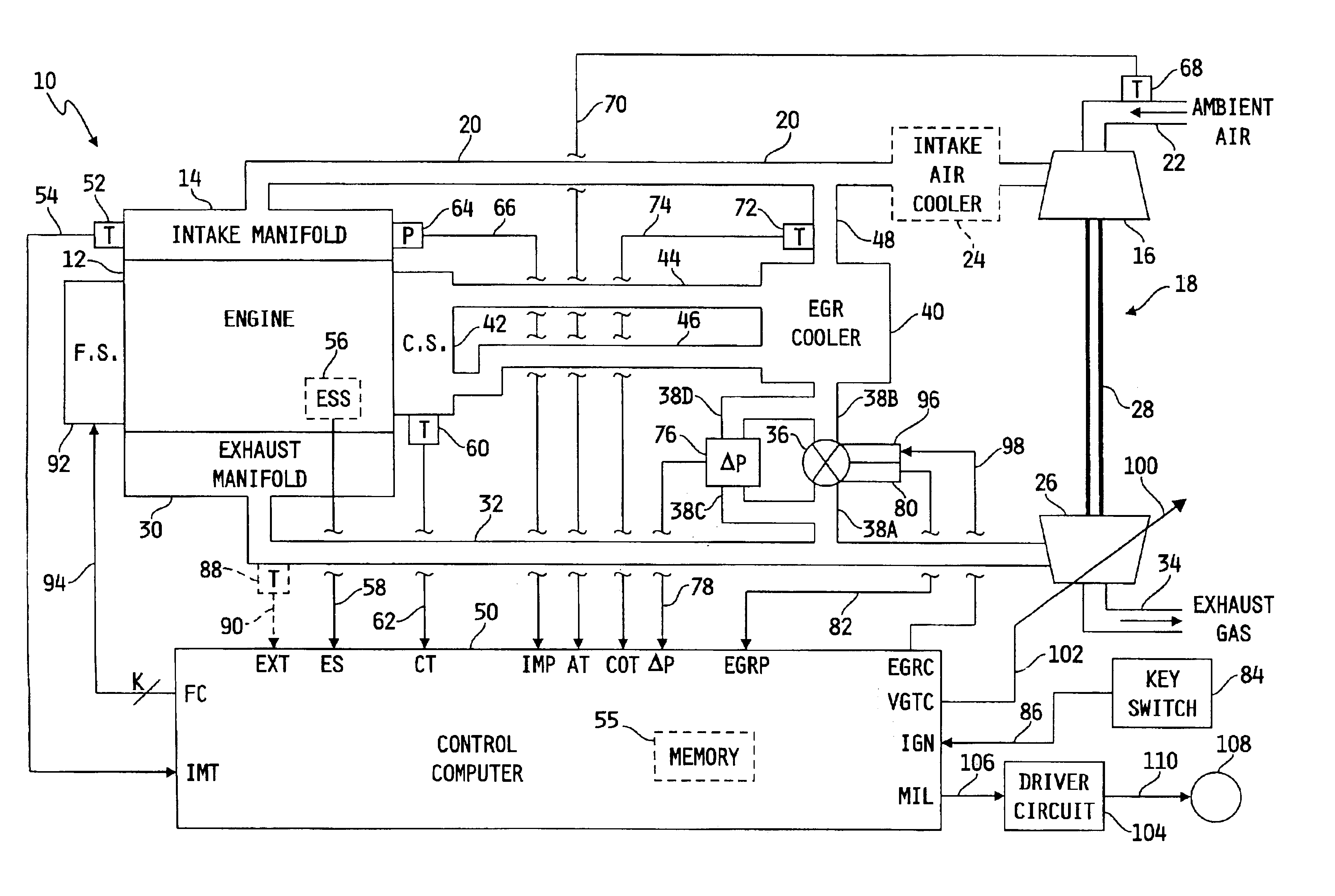
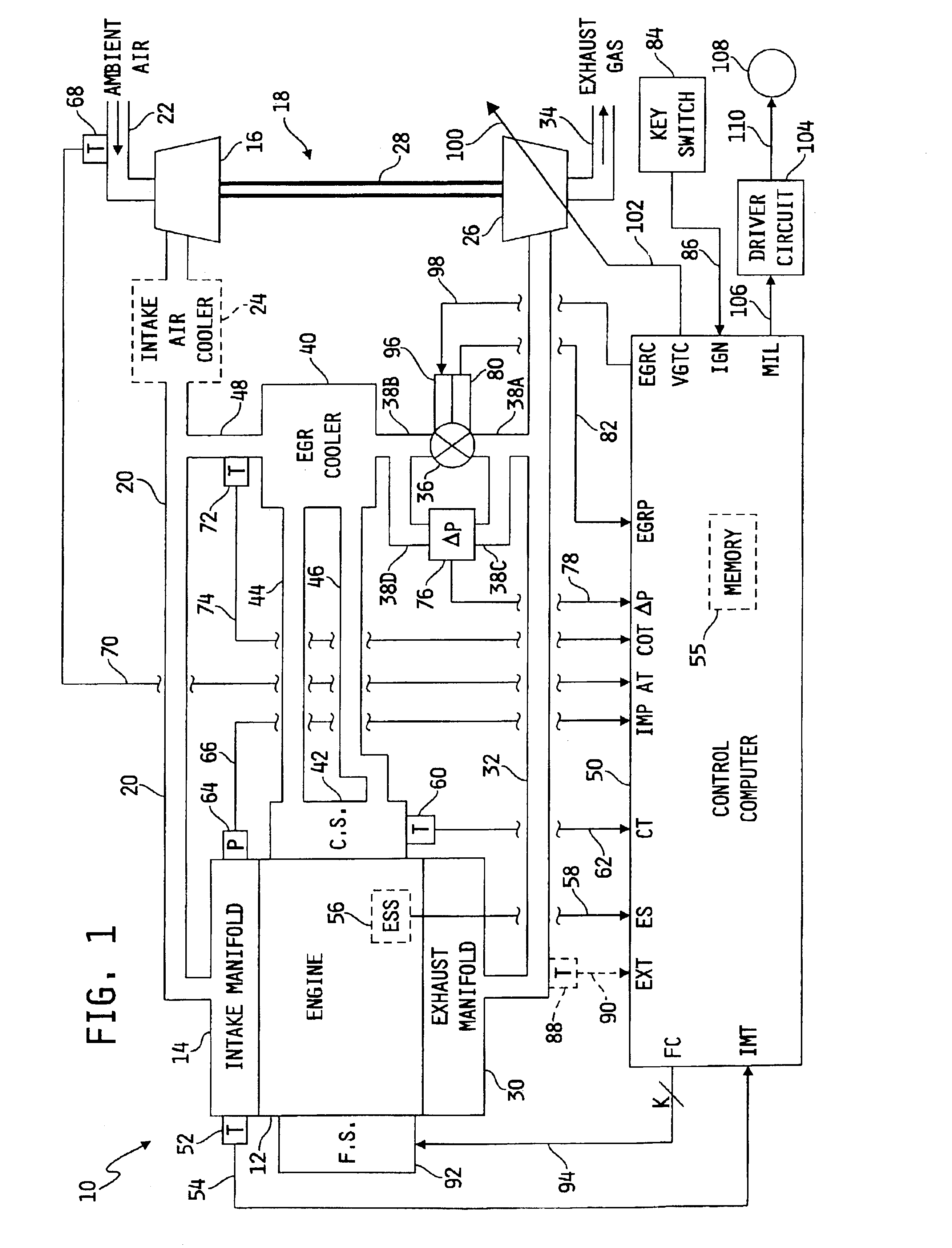
Referring now to FIG. 1, a diagram of one illustrative embodiment of a system 10 for diagnosing operation of an EGR cooler in an internal combustion engine is shown. System 10 includes an internal combustion engine 12 having an intake manifold 14 fluidly coupled to an outlet of a compressor 16 of a turbocharger 18 via an intake conduit 20, wherein the compressor 16 includes a compressor inlet coupled to an intake conduit 22 for receiving fresh ambient air therefrom. Optionally, as shown in phantom in FIG. 1, system 10 may include an intake air cooler 24 of known construction disposed in-line with intake conduit 20 between the turbocharger compressor 16 ...


PUM


Abstract

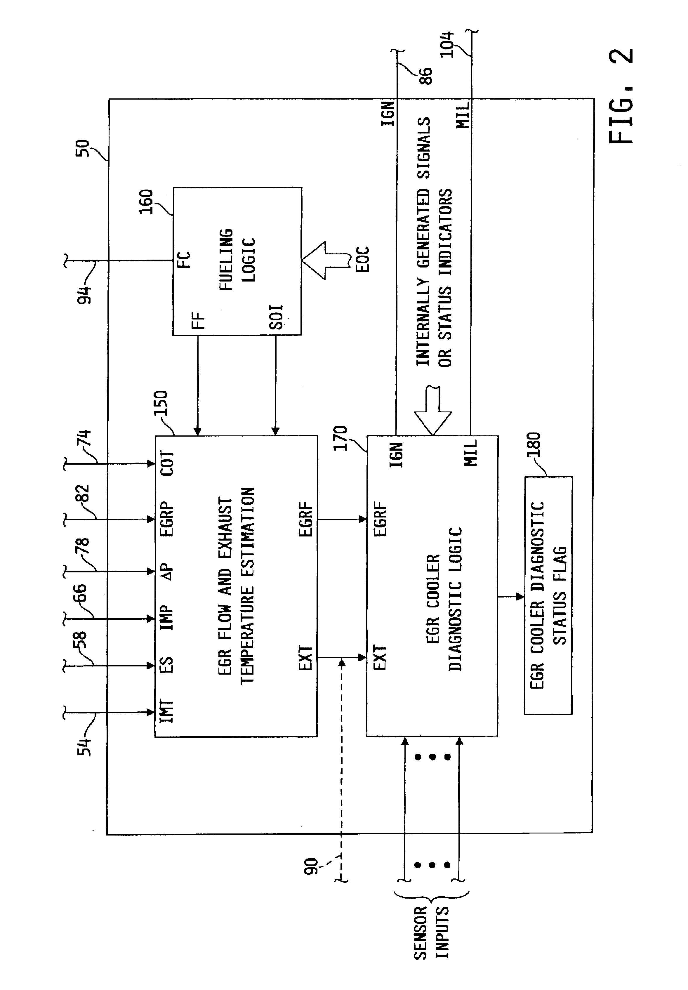
A system is disclosed for diagnosing operation of an EGR cooler disposed in-line with an EGR conduit fluidly coupled between an intake manifold and an exhaust manifold of the engine such that exhaust gas flowing through the EGR conduit also flows through the EGR cooler. The EGR cooler is coupled to an engine cooling system such that coolant fluid circulating through the engine also circulates through the EGR cooler. Means are provided for determining a temperature of exhaust gas produced by the engine, a temperature of exhaust gas exiting the EGR cooler, a temperature of the coolant fluid and a flow rate of exhaust gas through the EGR conduit. A control computer is configured to diagnose operation the EGR cooler as a function of the temperature of exhaust gas produced by the engine, the EGR cooler outlet temperature, the engine coolant temperature and the EGR flow rate.

Description

FIELD OF THE INVENTIONThe present invention relates generally to systems for monitoring the operation of an exhaust gas cooler in an exhaust gas recirculation (EGR) system, and more specifically to systems for diagnosing EGR cooler fouling conditions.BACKGROUND OF THE INVENTIONWhen combustion occurs in an environment with excess oxygen, peak combustion temperatures increase which leads to the formation of unwanted emissions, such as oxides of nitrogen (NOx). This problem is aggravated through the use of turbocharger machinery operable to increase the mass of fresh air flow, and hence increase the concentrations of oxygen and nitrogen present in the combustion chamber when temperatures are high during or after the combustion event.One known technique for reducing unwanted emissions such as NOx involves introducing chemically inert gases into the fresh air flow stream for subsequent combustion. By thusly reducing the oxygen concentration of the resulting charge to be combusted, the fu...

Claims


Application Information

Patent Timeline
IPC IPC(8): F02M25/07
CPCF02M25/0702F02M25/0754F02M25/0726F02M25/0707Y02T10/121F02M26/05F02M26/22F02M26/47F02M26/49
Inventor LI, XIAOQIUWANG, YUE YUN
Owner CUMMINS INC
Learn More