
Patient position monitoring device

a monitoring device and position technology, applied in the field of patient monitoring systems, can solve problems such as alarm to sound, and achieve the effects of reducing the likelihood of liquid contacting the circuitry, and enduring constant daily us

Inactive Publication Date: 2005-01-25
PROFESSIONAL SECURITY CORP
View PDF11 Cites 73 Cited by
  • Summary
  • Abstract
  • Description
  • Claims
  • Application Information

AI Technical Summary

Benefits of technology

The pad is comprised of a heavy duty, waterproof outer cover such as polyvinyl chloride (PVC) that allows the pad to withstand constant daily usage. It is important that the pad is waterproof since liquid can cause electrical devices to short circuit. It is particularly important that patient safety devices be waterproof since medical patients and elderly people may have more of a tendency to spill if they are in a weakened state. Furthermore, waterproofing is important because patients and elderly people may be incontinent. Therefore, the few openings that the pad does have are designed in such a way so as to minimize the likelihood of liquid contacting the circuitry.
The pad has an inside layer of corrugated plastic sheeting that adds rigidity to the pad. This allows the pad to function even if used on a soft mattress or if used by a lighter weight patient.
It is thus an object of this invention to provide a simple, cost effective way to monitor patients in their beds or wheelchairs.
It is further an object of this invention to provide a patient monitoring pad that has circuitry in a grid pattern throughout the pad which allows the device to function properly no matter where pressure is applied on its surface.
It is further an object of this invention to provide a patient monitoring pad that functions properly even on soft mattresses or if used by lighter weight patients.
It is further an object of this invention to provide a patient monitoring pad that comprises slip-resistant cushions to kept he pad in position to maintain efficiency of use.

Problems solved by technology

However, when weight is removed from the pad, air enters the pad and sponge through the air holes, causing the two layers of circuitry to become separated, which causes the alarm to sound.

Method used


Image

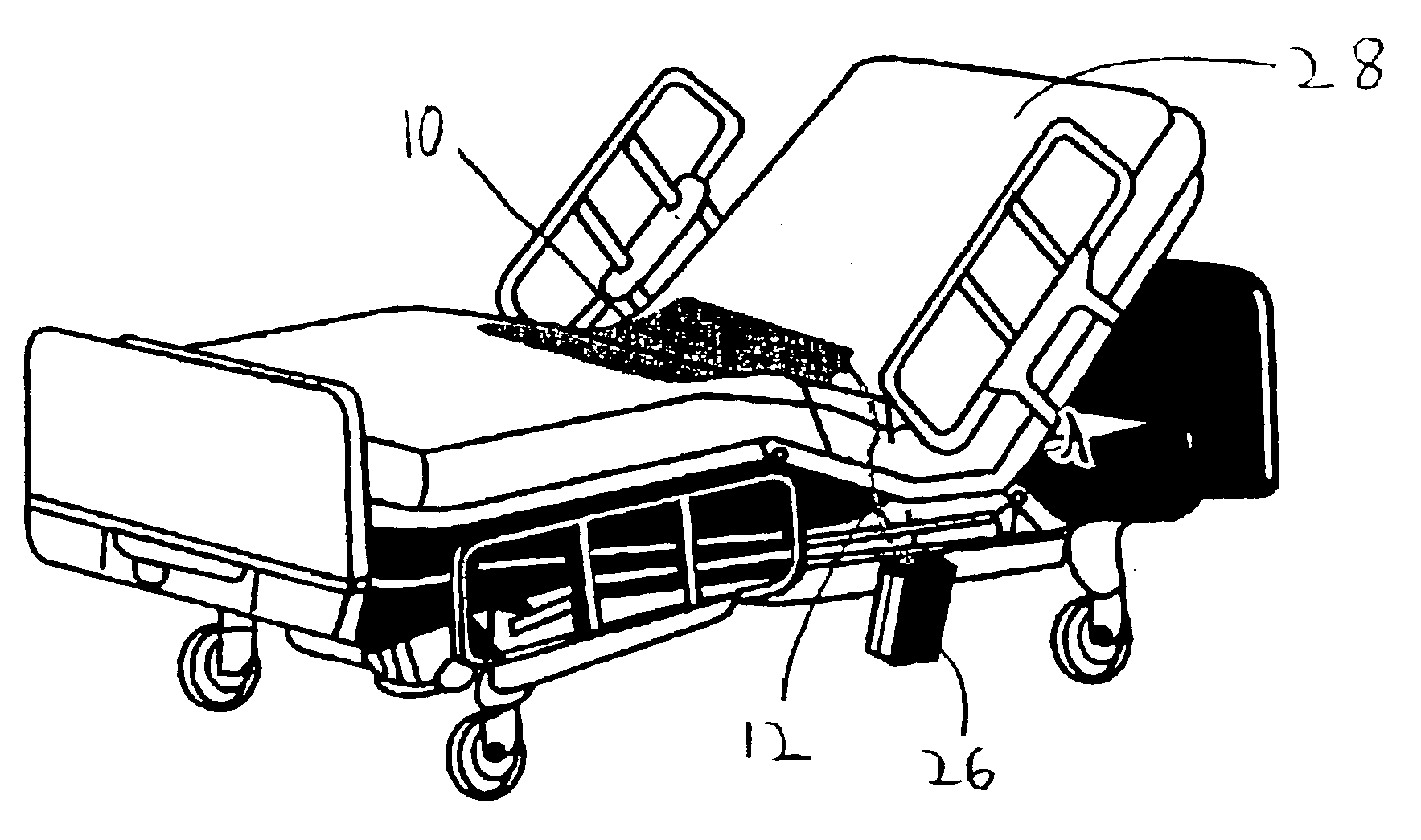
  • Patient position monitoring device
  • Patient position monitoring device
  • Patient position monitoring device

Examples


first embodiment

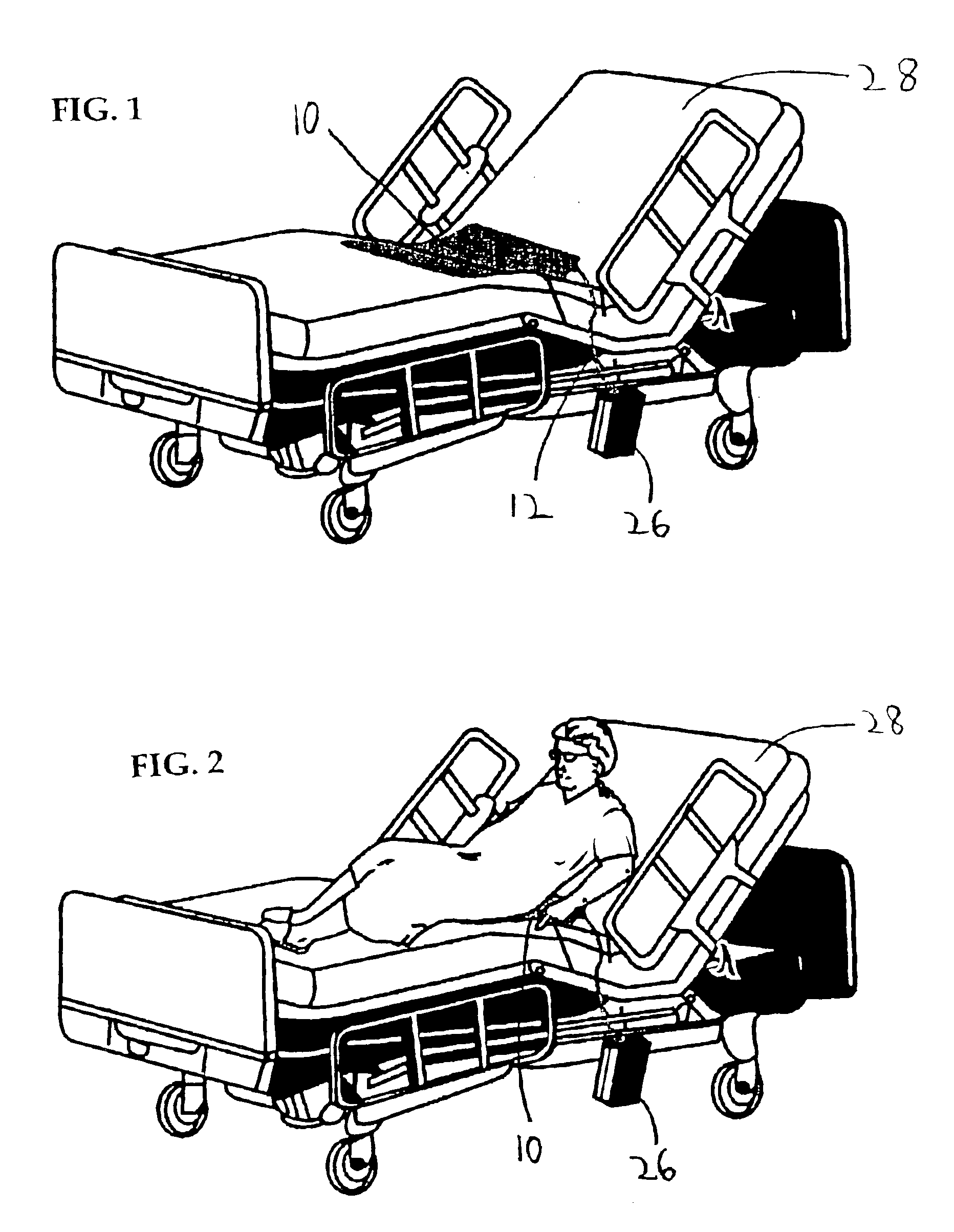
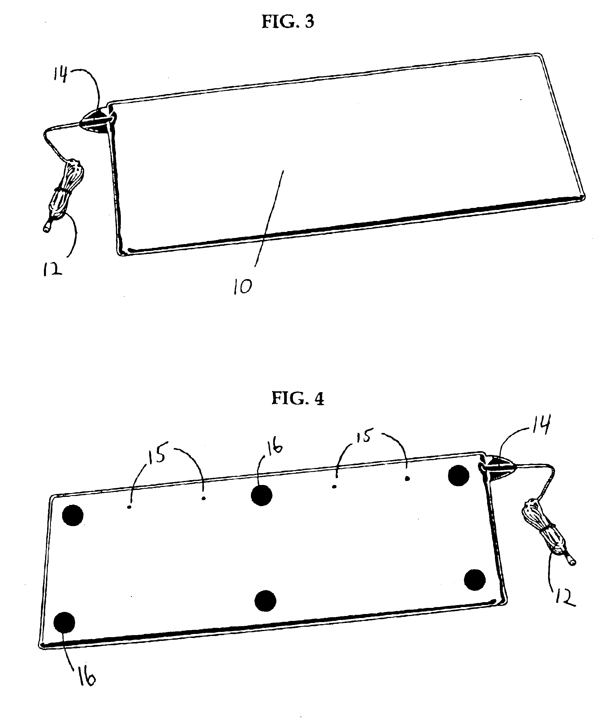
this invention is shown in FIGS. 3 and 4, which illustrate the top and bottom of the bed pressure pad 10 embodiment of the invention. The bed pressure pad 10 embodiment of the present invention is elongated so as to be placed underneath a patient's body as they lie in bed. The outside of the pad 10 is comprised of a heavy duty cover such as PVC that allows the pad 10 to be durable and withstand constant daily usage. FIG. 4 shows how the bottom of the pad 10 contains several slip retardant cushions 16, which keep the pad 10 from sliding out from under the patient.

FIG. 7 shows a cross-sectional view of the elements inside the pad 10. The circuitry 18 is folded in half so as to create an upper layer of circuitry and a lower layer of circuitry. There is a resilient material such as a high-density sponge 20 inserted between the layers of circuitry 18. This sponge 20 keeps the upper and lower layers of circuitry separated when no weight is on the pad 10. In order for the circuitry 18 insi...


PUM


Abstract

The disclosed invention is a patient monitoring system that employs a pressure sensitive pad. The pad is placed beneath a patient who is lying in bed or sitting in a chair. When weight is removed from the pad, an alarm is given. The pad comprises an upper layer of circuitry and a lower layer of circuitry. When the respective layers of circuitry are in contact, the alarm remains off, but when the layers of circuitry become separated, the alarm is given. This invention is generally for use in hospitals and nursing homes to alert caregivers when a patient falls out of a bed or a wheelchair; or if a patient otherwise leaves a bed or chair against the wishes of the caregiver. This situation is of special concern with elderly patients, post operational patients, and / or at night when nursing staffs are reduced.

Description

BACKGROUND OF INVENTIONThe present invention relates to a patient monitoring system, and more particularly to a pressure sensitive pad that sounds an alarm when weight is removed from it. There are many individuals who are physically challenged that are confined to beds or wheelchairs because of illness, disability, or age. Many of these people require assistance in living, but typically they cannot be continuously monitored throughout the day and night. If a patient attempts to leave a bed or chair, or falls out of a bed or chair, they may lie unconscious for a period of time endangering their health and life. To aid in the care of these individuals, medical safety devices have been developed that sound an alarm when a person falls or wanders off against the wishes of the caregiver. The noise produced by these safety devices alerts nurses or other aid personnel that the patient is in need of assistance.There are a variety of prior art devices that are used to monitor patients. In o...

Claims


Application Information

Patent Timeline
IPC IPC(8): A61B5/11A61G12/00G08B21/00G08B21/22
CPCA61B5/1115G08B21/22A61B5/6892A61B5/1117
Inventor OLSON, RICHARD T.
Owner PROFESSIONAL SECURITY CORP
Learn More