
Spectacle frame shape measuring apparatus

Inactive Publication Date: 2005-01-25
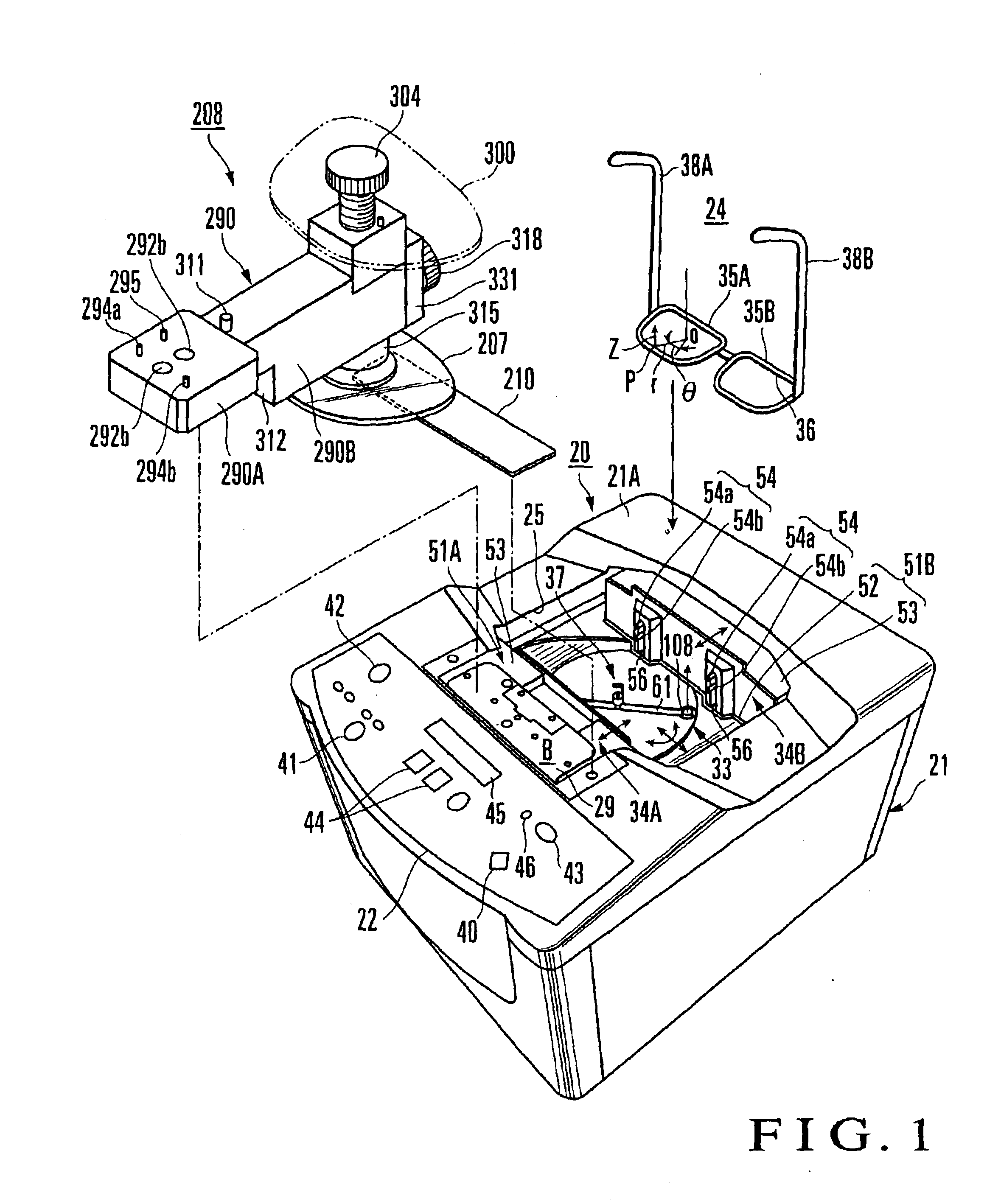
HOYA CORP
View PDF18 Cites 15 Cited by
  • Summary
  • Abstract
  • Description
  • Claims
  • Application Information

AI Technical Summary

Benefits of technology

[0041]It is a principal object of the present invention to provide a spectacle frame shape measuring apparatus which can reduce a measurement pressure applied to a contact portion of a measurement element with respect to a frame groove by inserting a movable member including the measurement element, a rod, and the like into the frame groove in an almost loadless state, prevent the contact portion from coming off the frame groove, deformation of rims, and the like, and accurately measure a displacement in the vertical direction.
[0042]It is another object of the present invention to provide a spectacle frame shape measuring apparatus which can perform accurate measurement without causing a measurement element to come off even frame grooves having different opening angles during the measurement, and correct a measurement value regardless of the opening angle.
[0043]It is still another object of the present invention to provide a spectacle frame shape measuring apparatus which can reliably evacuate a measurement element from a loading position to an evacuation position without causing it to stop during movement by forcibly evacuating it instead of by the self weight.

Problems solved by technology

The above spectacle frame shape measuring apparatus, however, involves various problems as described below.
As a consequence, the displacement Z in the vertical direction cannot be accurately measured.
According to the frame shape measuring apparatus disclosed in Japanese Patent Publication No. 1-23721 described above, the feeler in the form of an abacus counter tends to come off a thin frame groove, and it is difficult to smoothly control the rotation of the feeler.
In addition, if the opening angle of a frame groove changes, the contact position between the feeler in the form of an abacus counter and the frame groove changes, resulting in a measurement error in the displacement r in the radial direction.
In addition, since a unit or attachment for measuring the opening angle α of the frame groove 2 is required, the manufacturing cost of the measuring apparatus itself increases.
In a conventional Z-axis measuring unit 13 shown in FIG. 30, as in the Z-axis measuring unit A, a sensor rod 13B integrally extends from the lower end of the rod 7, and hence the total length of the rod 7 increases, resulting in difficulty in decreasing the height of the spectacle frame shape measuring apparatus.
If, therefore, the pushing member moves a long distance, the pushing member must be rotated many times. Therefore, the template cannot be attached or detached at one touch, and it takes much time for attachment / detachment, resulting in poor handling.
For this reason, the dummy lens cannot be attached or detached at one touch either; a long period of time is required for attachment or detachment.

Method used


Image

  • Spectacle frame shape measuring apparatus
  • Spectacle frame shape measuring apparatus
  • Spectacle frame shape measuring apparatus

Examples


Embodiment Construction

tances R when the opening angles α of frame grooves are 110°, 100°, and 90°, and the diameter D of the contact portion is set to 2.2 mm;

[0072]FIGS. 18A, 18B, and 18C are views showing distances R when the opening angles α of frame grooves are 110°, 100°, and 90°, and the diameter D of the contact portion is set to 2.4 mm;

[0073]FIG. 19 is a sectional view of a holder;

[0074]FIG. 20 is a bottom view of the holder;

[0075]FIG. 21 is a view for explaining a procedure for mounting a frame template;

[0076]FIG. 22 is a view for explaining a procedure for mounting the frame template;

[0077]FIG. 23 is a view for explaining a procedure for mounting the frame template;

[0078]FIG. 24 is a view showing the mount position of the holder and the positions of sensors when a left frame template is measured;

[0079]FIG. 25 is a view showing the mount position of the holder and the positions of the sensors when a left lens is measured;

[0080]FIG. 26 is a view showing the mount position of the holder and the pos...


PUM


Abstract

A spectacle frame shape measuring apparatus includes a measurement element holding mechanism. The measurement element holding mechanism holds a measurement element in a substantially loadless state along a frame groove formed in the inner circumferential surface of a rim of a spectacle frame. The measurement element holding mechanism includes a rod, balance spring, and evacuating mechanism. The rod is vertically movable and has an upper end portion on which the measurement element is mounted. The balance spring pushes the rod upward to hold the measurement element at a loading position during shape measurement. The evacuating mechanism regularly evacuates the measurement element to an evacuation position, thereby performing three-dimensional measurement of a rim shape. A spectacle frame shape measuring apparatus holder is also disclosed.

Description

BACKGROUND OF THE INVENTION[0002]The present invention relates to a spectacle frame shape measuring apparatus for measuring the frame shape of a spectacle frame and the shape of a frame template or lens and a holder used to mount the frame template and lens on the spectacle frame shape measuring apparatus.[0003]The shape of a frame rim (rim) of a spectacle frame when viewed from the top is generally curved along the face of a wearer. For this reason, shape measurement is performed in three dimensions by a spectacle frame shape measuring apparatus. The measurement data is therefore expressed in a cylindrical coordinate system with r (the displacement of a measurement element in the radial direction), θ (the displacement of the measurement element in the rotational direction in a horizontal plane with reference to an arbitrary point on the measurement element), and Z (the displacement of the measurement element in the height direction). For this reason, the spectacle frame shape measu...

Claims


Application Information

Patent Timeline
IPC IPC(8): B24B9/14B24B9/06G01B21/20
CPCG01B5/20B24B9/144G01B5/00
Inventor IGARASHI, TAKASHIAKIYAMA, HISANORIJINBO, MASAHIROSATO, RYOSUKEDAIMARU, TAKASHI
Owner HOYA CORP
Learn More