Mercury lamp, lamp unit, method for producing mercury lamp and electric lamp

a mercury lamp and lamp unit technology, applied in the direction of incandescent lamp energy saving, tube/lamp factory adjustment, sustainable buildings, etc., can solve the problems of insufficient or limited exchange of lamps, difficult operation of lamps, and large problem of short lifetime of conventional lamps b>1000/b>, so as to prevent blackening of luminous bulbs

Inactive Publication Date: 2005-01-18
PANASONIC CORP
View PDF21 Cites 8 Cited by
  • Summary
  • Abstract
  • Description
  • Claims
  • Application Information

AI Technical Summary

Benefits of technology

According to the present invention, the mole number of halogen is larger than the sum of the total mole number of metal elements that are present in the luminous bulb (except tungsten and mercury) and the mole number of the tungsten present in the luminous bulb that has been evaporated from the electrodes during lamp operation. Therefore, the blackening of the luminous bulb can be prevented. As a result, a high-pressure discharge lamp having a long life can be provided. Even if the bulb wall load of the luminous bulb is 80 W / cm2 or more, the blackening of the luminous bulb can be prevented. Consequently, the present invention can provide a high-pressure discharge lamp that has a long life (for example, 5000 hours to 10000 hours or more), even if the lamp is used under high output conditions that end the lamp life early in the prior art.

Problems solved by technology

Furthermore, it was found that in these conventional lamps, as the operation time becomes longer, the voltage at the start of discharge becomes higher, so that the lamps become difficult to operate.
However, when the conventional lamp 1000 is used for television (projection television) for ordinary homes, the short lifetime of the conventional lamp 1000 is a large problem.
Furthermore, it is in demand that exchange of lamps is unnecessary or is limited to a number of times as small as possible.
However, the conventional lamp 1000 cannot provide the lamp lifetime of 5000 hours to 100000 hours or more, which is required by projection type liquid crystal televisions.

Method used


Image

  • Mercury lamp, lamp unit, method for producing mercury lamp and electric lamp
  • Mercury lamp, lamp unit, method for producing mercury lamp and electric lamp
  • Mercury lamp, lamp unit, method for producing mercury lamp and electric lamp

Examples


embodiment 1

(Embodiment 1)

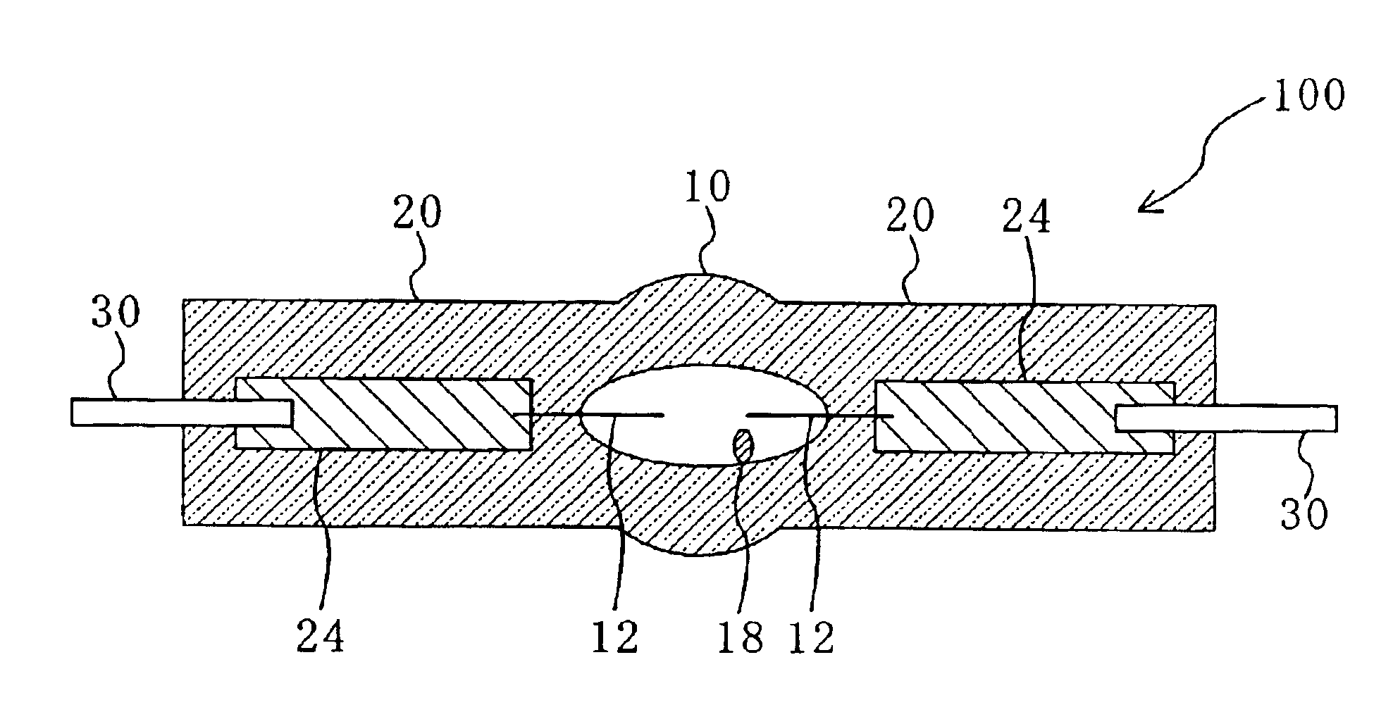
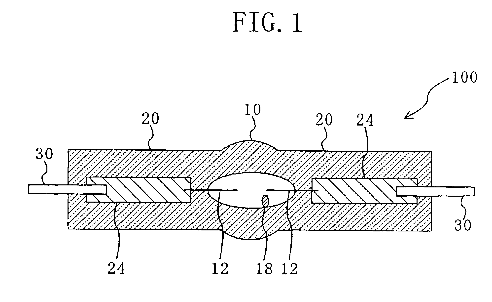
Embodiment 1 of the present invention will be described with reference to FIGS. 1 to7.

First, FIG. 1 schematically shows the structure of a high-pressure discharge lamp 100 of the present invention. The discharge lamp 100 includes a luminous bulb 10 made substantially of quartz glass and electrodes 12 made substantially of tungsten arranged in the luminous bulb 10. At least a rare gas and halogen are enclosed in the luminous bulb 10, and the mole number of the halogen enclosed in the luminous bulb 10 is larger than the sum of the total mole number of metal elements (except the tungsten element and the mercury element) that have the property of bonding to halogen and are present in the luminous bulb 10, and the mole number of the tungsten present in the luminous bulb 10 by evaporation from the electrodes 12 during lamp operation.

In this embodiment, a pair of sealing portions (seal portions) 20 are coupled to both ends of the luminous bulb 10 of the lamp 100, and the seal...

embodiment 2

(Embodiment 2)

Embodiment 2 of the present invention will be described with reference to FIGS. 7 to 9. In this embodiment, a method for producing a high-pressure discharge lamp whose residual strain in the luminous bulb is smaller than that of the conventional lamp will be described.

The method for producing a high-pressure discharge lamp of this embodiment includes a process of completing a shape of a high-pressure discharge lamp so that a finished lamp shaped structure is obtained and then removing the residual strain of the finished lamp shaped structure. The process of removing the residual strain of the finished lamp shaped structure is a heat treatment process (annealing), and is performed to the finished lamp shaped structure after the finished lamp shaped structure was obtained according to a known lamp production process.

In a conventional method for producing a high-pressure discharge lamp, after a finished lamp shaped structure is obtained by a lamp production process, this ...

embodiment 3

(Embodiment 3)

The high-pressure discharge lamp 100 of Embodiment 1 can be formed into a lamp unit in combination with a reflecting mirror. FIG. 10 schematically shows the cross-section of a lamp unit 500 provided with the lamp 100 of Embodiment 1.

The lamp unit 500 includes the discharge lamp 100 including a substantially spherical luminous bulb 10 and a pair of sealing portions 20 and a reflecting mirror 60 for reflecting light emitted from the discharge lamp 100.

The reflecting mirror 60 is designed to reflect the light radiated from the discharge lamp 100 such that the light becomes a parallel luminous flux, a condensed luminous flux converged on a predetermined small area, or a divergent luminous flux equal to that emitted from a predetermined small area. As the reflecting mirror 60, a parabolic reflector or an ellipsoidal mirror can be used, for example.

In this embodiment, a lamp base 55 is attached to one sealing portion 20 of the lamp 100, and an external lead extending from th...


PUM


Abstract

The present invention provides a high-pressure discharge lamp 100 including a luminous bulb 10 enclosing at least a rare gas and halogen in the bulb and made substantially of quartz glass; and an electrode 12 made substantially of tungsten and disposed in the luminous bulb. The mole number of the halogen is larger than the sum of the total mole number of metal elements (except the tungsten element and the mercury element) that have the property of bonding to the halogen and are present in the luminous bulb 10 and the mole number of the tungsten present in the luminous bulb by evaporation from the electrode 12 during lamp operation.

Description

TECHNICAL FIELDThe present invention relates to a high-pressure discharge lamp, a lamp unit, a method for producing a high-pressure discharge lamp and an electric lamp. In particular, the present invention relates to a high-pressure discharge lamp used for general illumination, and liquid crystal projectors or projection type liquid crystal television in combination with a reflecting mirror.BACKGROUND ARTSpecific examples of a conventional high-pressure discharge lamp include the high-pressure mercury vapor discharge lamps disclosed in Japanese Laid-Open Patent Publication No. 2-18561 and Japanese Patent Publication No. 2980882. FIG. 13 schematically shows a structure of the high-pressure discharge lamps disclosed in these publications. Hereinafter, the conventional high-pressure discharge lamp 1000 will be described with reference to FIG. 13.The lamp 1000 includes a luminous bulb (bulb) 110 made of quartz glass and a pair of sealing portions (seal portions) 120 coupled to both ends...

Claims


Application Information

Patent Timeline
Patent Type & Authority Patents(United States)
IPC IPC(8): H01J61/86H01J61/20H01J61/12H01J61/30H01J61/84H01K1/00H01K1/50H01J9/44H01J61/073
CPCH01J9/44H01J61/0732H01J61/125H01J61/86H01K1/50H01J61/302Y02B20/12Y02B20/00H01J61/30
Inventor HORIUCHI, MAKOTOKAI, MAKOTOTAKEDA, MAMORUICHIBAKASE, TSUYOSHISEKI, TOMOYUKIKITAHARA, YOSHIKIMORI, TOSHIOTAKEUCHI, YASUO
Owner PANASONIC CORP
Why Eureka
Try Eureka