Eureka AIR delivers breakthrough ideas for toughest innovation challenges, trusted by R&D personnel around the world.

Memory wire actuated control valve

a control valve and memory wire technology, applied in the direction of valve operating means/release devices, water supply installation, mechanical equipment, etc., can solve the problems of excessive water hammer, relatively heavy and bulky solenoid,

Inactive Publication Date: 2005-01-18
SCOTT LOREN W
View PDF13 Cites 172 Cited by
  • Summary
  • Abstract
  • Description
  • Claims
  • Application Information

AI Technical Summary

Benefits of technology

The memory wire actuator and fluid control valve of the present invention has numerous applications, including industrial machinery, commercial and residential water systems, and is particularly well-suited to irrigation systems. In a common irrigation system, a main water supply line feeds into a plurality of control valves which may be opened or closed to control the flow of water to the outlet of the control valves. The outlet of the control valves are connected to a li...

Problems solved by technology

For one, a solenoid is relatively heavy and bulky because it requires an electrical coil and a magnetizable plunger element.
In addition, solenoid devices have fast actuation times which can result in excessive water hammer.

Method used


Image

  • Memory wire actuated control valve
  • Memory wire actuated control valve
  • Memory wire actuated control valve

Examples


Embodiment Construction

Embodiments of the invention will now be described with reference to the accompanying Figures, wherein like numerals refer to like elements throughout. The terminology used in the description presented herein is not intended to be interpreted in any limited or restrictive manner, simply because it is being utilized in conjunction with a detailed description of certain specific embodiments of the invention. Furthermore, embodiments of the invention may include several novel features, no single one of which is solely responsible for its desirable attributes or which is essential to practicing the inventions herein described.

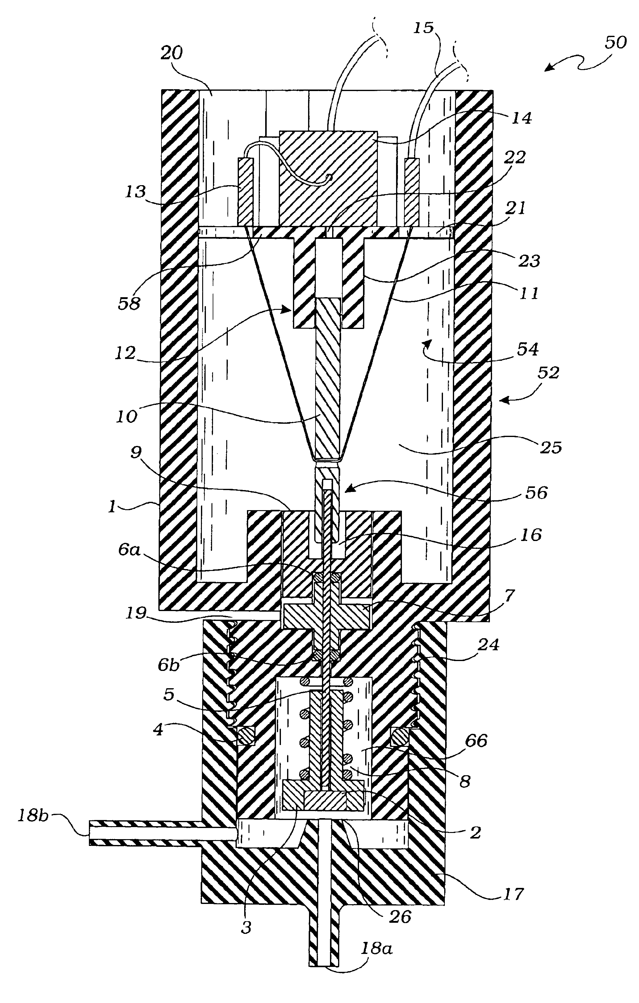
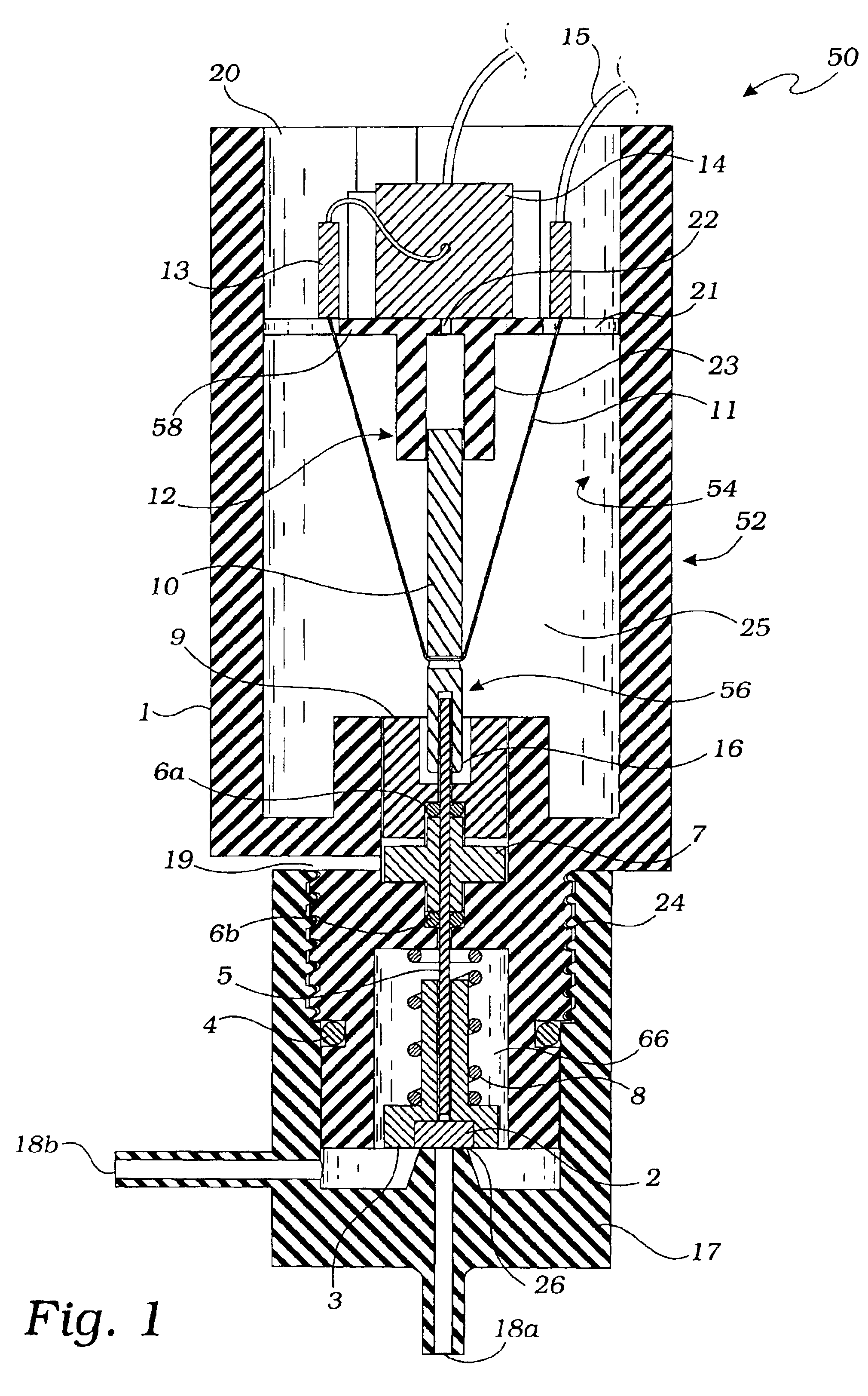
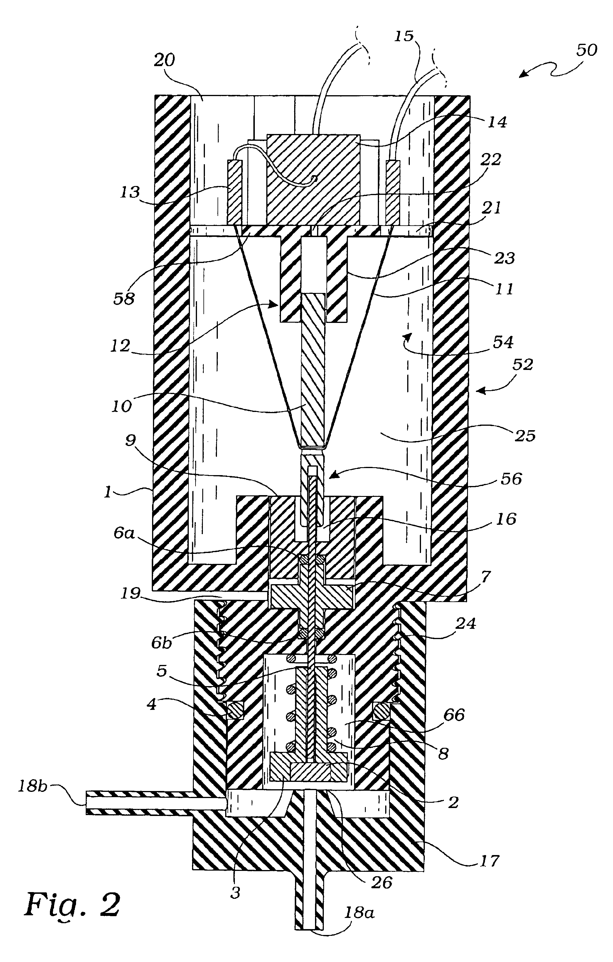
Referring now to the drawings, FIG. 1 is a cross-sectional view of a memory wire actuated control valve 50 according to the present invention. The wire actuated control valve 50 comprises a memory wire actuator assembly 52 operably coupled to a pilot valve assembly 17. The memory wire actuator assembly 52 may be removably attached to the pilot valve assembly 17 by ...


PUM


Abstract

A memory wire actuated control valve comprises a memory wire actuator operatively coupled to a fluid control valve. The memory wire actuator includes a housing having an interior cavity enclosing an electrical platform assembly, an activation wire and a transfer mechanism. The activation wire is formed of a shape memory alloy, often called a “memory wire” or “muscle wire.” The activation wire is electrically connected to the electrical platform and mechanically coupled to the transfer mechanism. The actuator is activated by conducting electrical current through the activation wire causing the wire to contract thereby actuating the transfer mechanism. The transfer mechanism is operable coupled to the fluid control valve such that actuated and de-actuating the transfer mechanism open and closes the valve.

Description

FIELD OF THE INVENTIONThe present invention relates generally to the field of electrically operated devices, and more specifically to an improved fluid control valve and method of manufacturing and using the same. Such valves have application in a variety of fields for controlling fluid flow, including irrigation, automotive, and industrial applications.BACKGROUND OF THE INVENTIONFluid control valves are typically comprised of a valve assembly and an actuator which applies a motive force to a plunger rod or other coupling device of the valve assembly to open and close the valve. The most common actuator used with fluid control valves is a solenoid device. A solenoid actuator generally consists of an electrical coil which when energized with an electrical potential, produces an electromagnetic field that is utilized to apply a motive force to a magnetized work element such as a plunger.Many fluid control valves have been previously disclosed. For example, U.S. Pat. No. 5,979,482, the...

Claims


Application Information

Patent Timeline
IPC IPC(8): E03C1/00E03B1/00F16K31/02F16K31/64F16K31/66F17D1/00
CPCF16K31/025
Inventor SCOTT, LOREN W.
Owner SCOTT LOREN W
Why Eureka
Eureka Blog
Learn More