
Method for cross-connecting optical signals at high speed

a cross-connecting and high-speed technology, applied in the field of optical communication, can solve the problems of large beam divergence, large mirror structure, difficult to maintain very narrow beam widths across the lateral extent of a multi-channel cross-bar switch, etc., and achieve the effect of increasing the number of output channels per input channel and speeding up the switch

Inactive Publication Date: 2005-01-11
CREO SRL
View PDF18 Cites 12 Cited by
  • Summary
  • Abstract
  • Description
  • Claims
  • Application Information

AI Technical Summary

Benefits of technology

A micro-machined mirror optical crossbar switch directs the light beams of input signal channels to selected output channels by manipulating the focal lengths of adaptive optical elements to ensure that the light beam of any given incoming channel is always focused at the position of the reflective device that is selected to switch that beam. This allows the reflective device to be smaller and switch faster and allows the number of output channels per input channel to be increased.

Problems solved by technology

While materials choice for the reflective element can help to make this frequency as high as possible, the very size of the mirror structure is core issue.
This requirement presents a problem in that the small apertures involved in the cores of the optical fibers carrying light signals lead to considerable beam divergence, which is typically addressed via micro-lenses to collimate the emerging beam.
However, this collimation is also inherently limited by the aforementioned aperture dimensions with the result that it is very difficult to maintain very narrow beam widths across the lateral extent of a multi-channel crossbar switch.

Method used


Image

  • Method for cross-connecting optical signals at high speed
  • Method for cross-connecting optical signals at high speed
  • Method for cross-connecting optical signals at high speed

Examples


Embodiment Construction

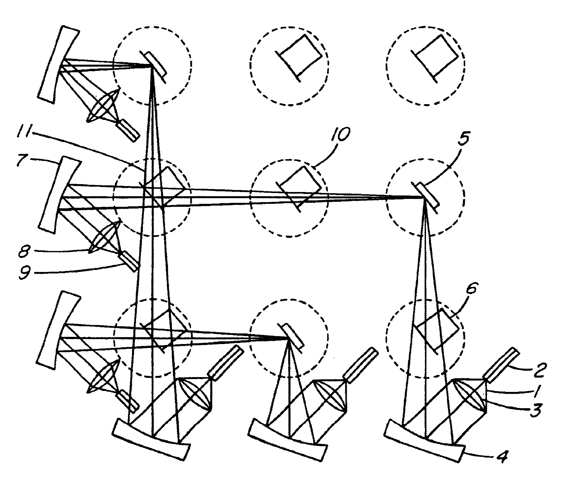
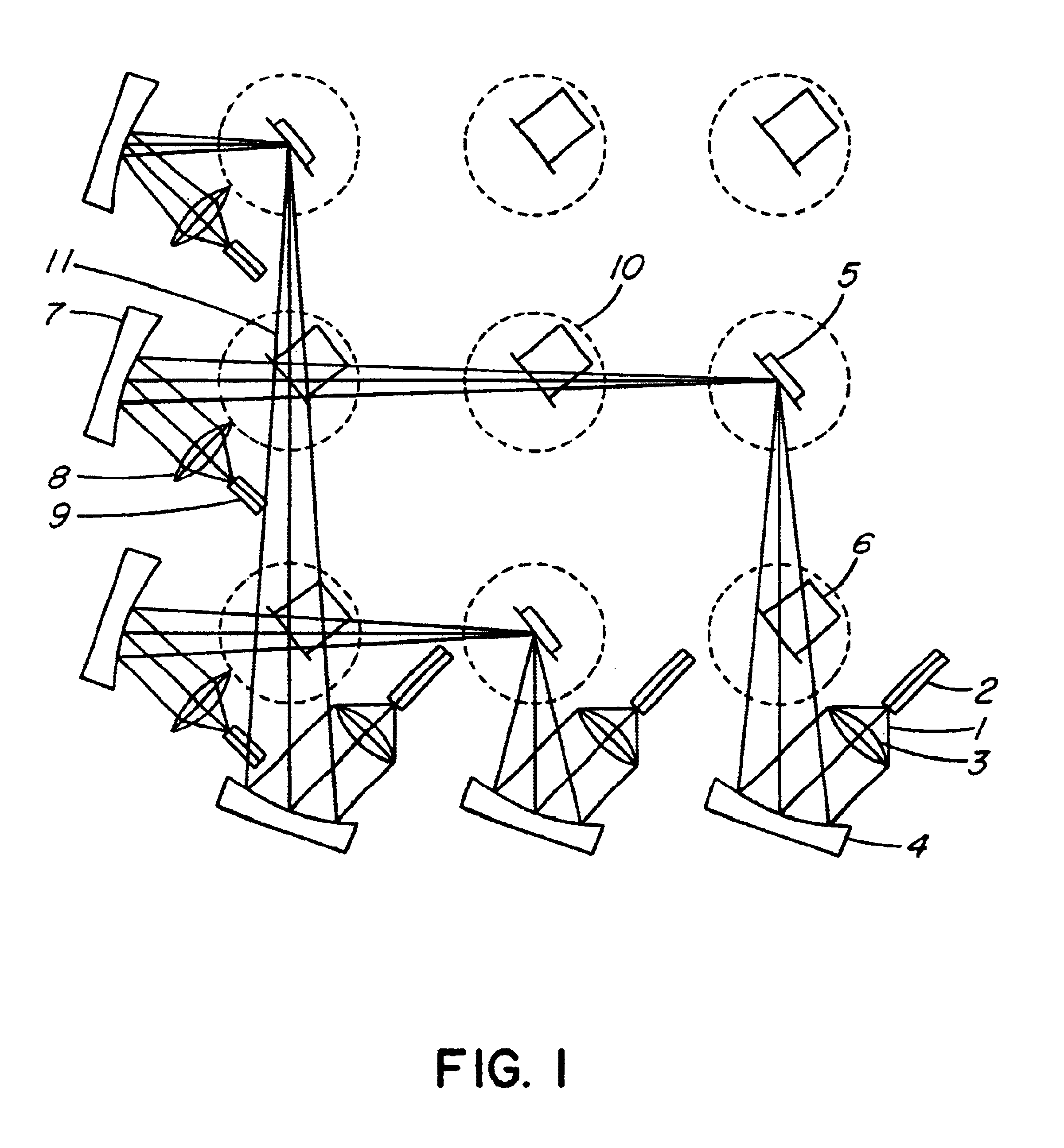
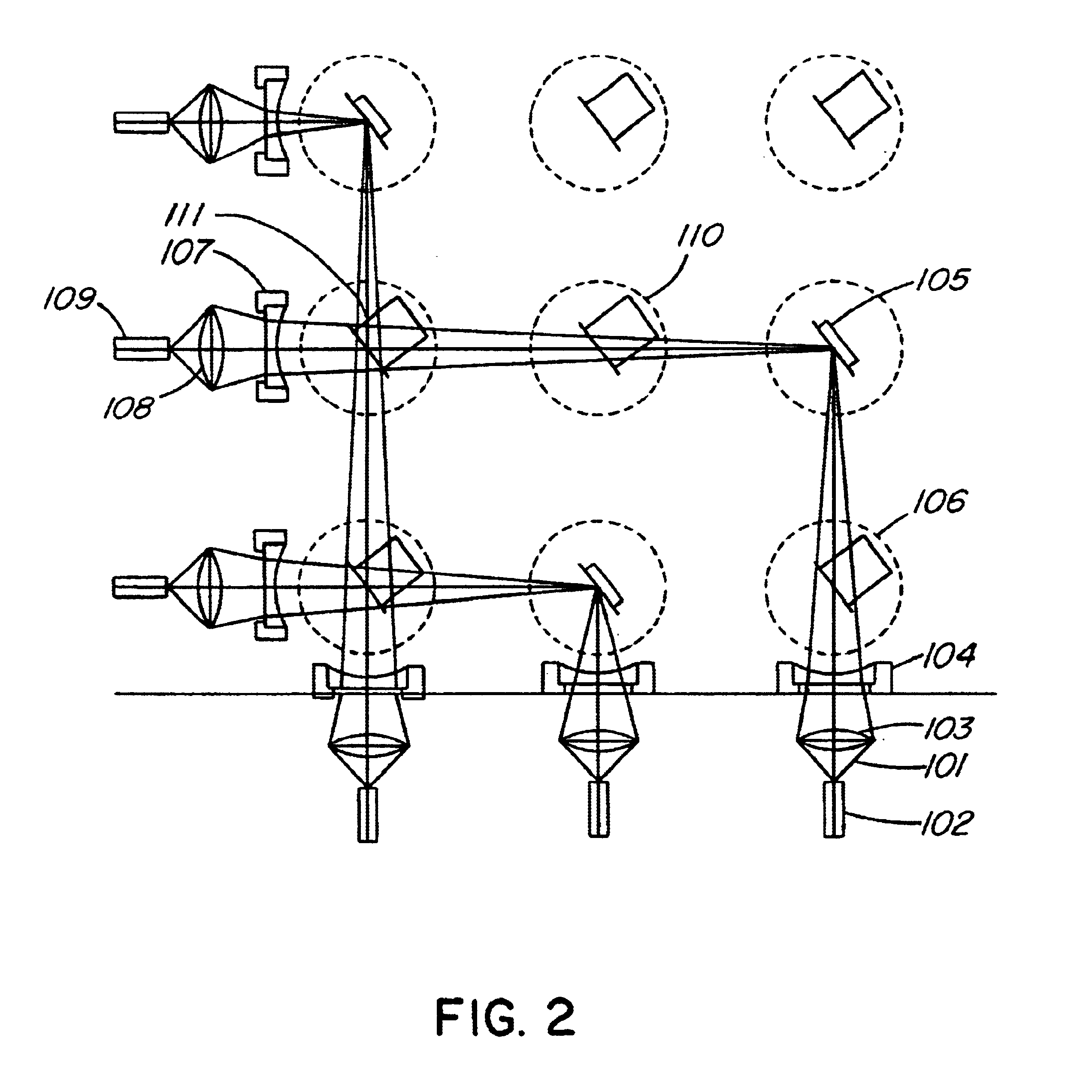
FIG. 1 shows the preferred embodiment of the present invention as a 3×3 optical crossbar switch, comprising three input channels along the bottom horizontal and three output channels along the left vertical. The crossbar switch has individually addressable micro-machined mirrors arranged in three rows and three columns with three mirrors in a column per input channel. The invention is particularly useful for larger crossbar switches, from 10×10 to 1000×1000, however a 3×3 example is shown here for the sake of clarity.

Referring now to FIG. 1, an input signal light beam 1 enters the crossbar switch through the core of optical fiber 2. Due to the very small optical aperture represented by the core of the fiber, the beam 1 has very large divergence as shown in FIG. 1. This divergent light is collected and focused by micro-lens 3. Micro-machined reflective membrane device 4 is employed to adjust the focal point of input signal light beam 1. Such devices are well-known in the art of micro...


PUM


Abstract

A micro-machined mirror optical crossbar switch directs the light beams of input signal channels to selected output channels by manipulating the focal lengths of adaptive optical elements to ensure that the light beam of any given incoming channel is always focused at the position of the reflective device that is selected to switch that beam. This allows the reflective device to be smaller and switch faster and allows the number of output channels per input channel to be increased.

Description

FIELD OF THE INVENTIONThe invention to the field of optical communication and in particular to the cross-connection of optical communication channels.BACKGROUND OF THE INVENTIONThe field of communications has benefited enormously from the introduction of optical communications technology. Fundamentally, this technology exploits the inherent bandwidth potential of the light itself as a carrier. As this technology natures, the need for the direct optical processing of signals is becoming greater. Much of the communications infrastructure in operation in the field relies on optical signals being converted back to electrical form for certain processing and management functions. Direct optical processing has the benefit of avoiding the need for such conversion with its associated costs, losses and amplification requirements.One of the fundamental building blocks of an optical communications system is the optical cross-connect or optical crossbar switch. These devices function to selectab...

Claims


Application Information

Patent Timeline
Patent Type & Authority Patents(United States)
IPC IPC(8): G02B6/35H04Q11/00
CPCG02B6/3582H04Q11/0005G02B6/3512G02B6/3546H04Q2011/0058H04Q2011/0026G02B6/3584
Inventor RICHARDSON, DOUGLAS
Owner CREO SRL
Learn More