
Signal processing system with baseband noise modulation and noise fold back reduction

Active Publication Date: 2005-01-11
CIRRUS LOGIC INC
View PDF6 Cites 27 Cited by
  • Summary
  • Abstract
  • Description
  • Claims
  • Application Information

AI Technical Summary

Benefits of technology

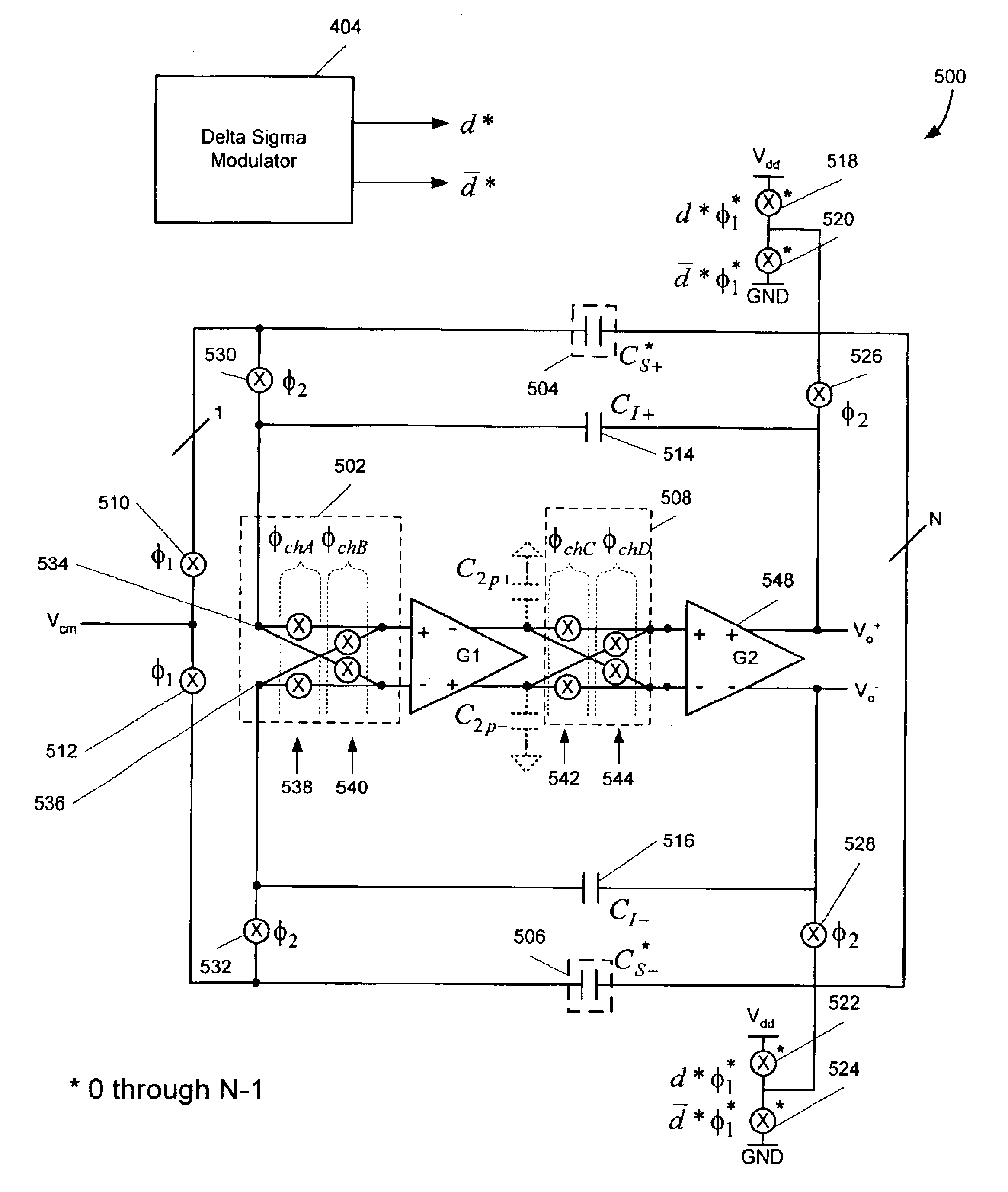
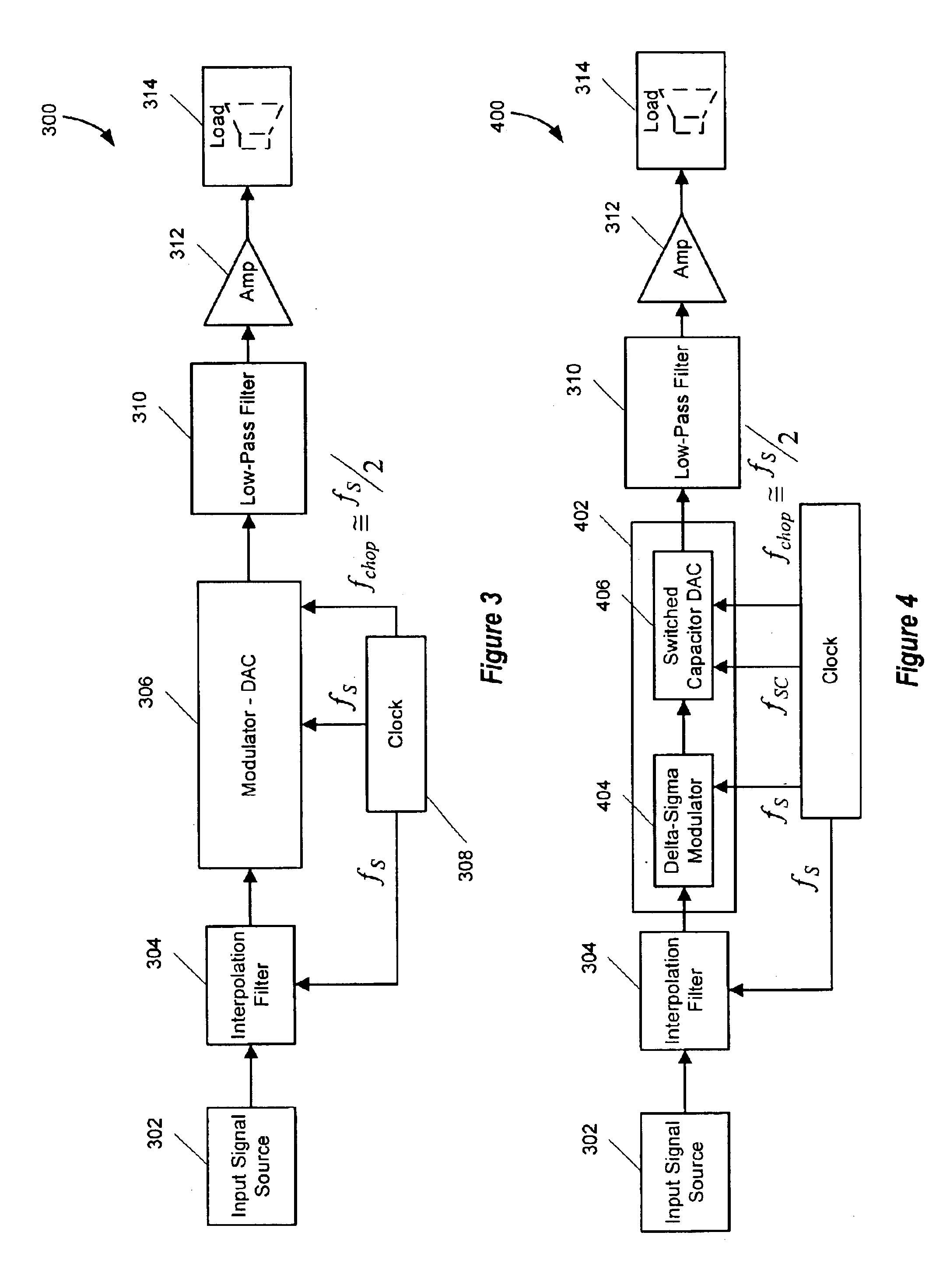
In another embodiment of the present invention, a method of converting a digital input signal, sampled at a frequency fS and having frequencies within a baseband, into a representative analog signal, modulating out of the baseband low frequency noise components associated with a digital to analog converter (“DAC”) gain stage, and reducing fold back of quantization noise, frequency components residing outside the baseband, the method includes modulating a DAC input signal, which is derived from the digital input signal and the quantization noise by a modulation frequency of approximately or equal to fS / 2. The method further includes providing the modulated DAC input signal to the DAC gain stage. The method also includes demodulating output signals of the DAC gain stage by a demodulation frequency of approximately or equal to fS / 2 to allow frequency components of the input signal to fold back into the baseband, to prevent fold back into the baseband of the quantization noise frequency components, and modulate the noise associated with the gain stage substantially out of the baseband.

Problems solved by technology

Components used to implement signal processing technology often generate unwanted noise.
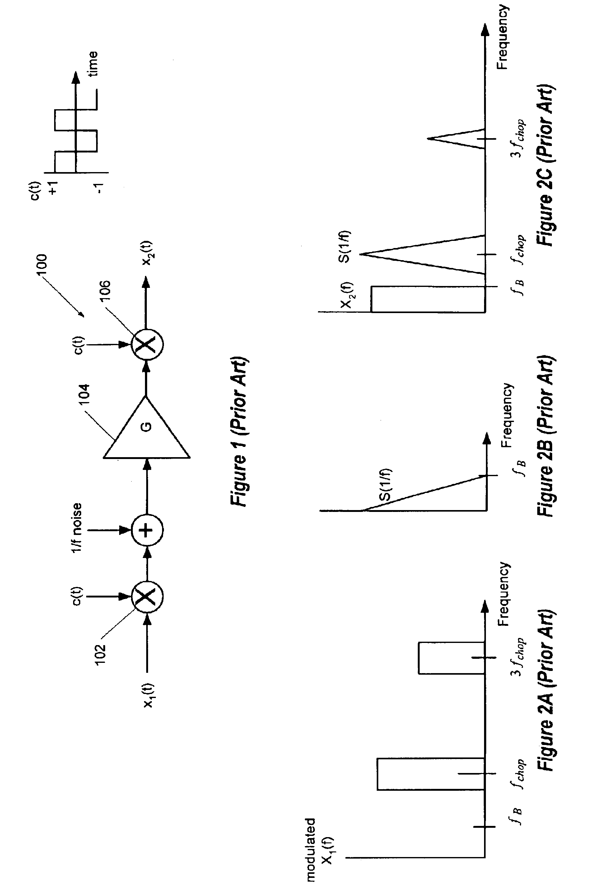
In the process of conversion, DACs often generate noise through, for example, quantization errors (“quantization noise”) and low frequency 1 / f noise.
Nevertheless, some post modulation processing, such as a post-modulation digital to analog conversion and low pass filtering, introduces noise into the audio baseband.
One common type of noise generated in post modulation processing circuits, such as metal oxide semiconductor gain stages, is 1 / f noise which, as the nomenclature implies, has relatively high energy at low frequencies that rapidly diminishes at higher frequencies.

Method used


Image

  • Signal processing system with baseband noise modulation and noise fold back reduction
  • Signal processing system with baseband noise modulation and noise fold back reduction
  • Signal processing system with baseband noise modulation and noise fold back reduction

Examples


Embodiment Construction

Signal processing technology operates on analog, digital and mixed signals (analog and digital). For example, audio signals, representing a signal of interest and having frequency components residing within a baseband, begin as analog signals and are often digitized through sampling, and converted back into analog output signals using a digital-to-analog converter (DAC). Audio frequency analog output signals produce sound through a loud speaker, headphones, or other output device. Embodiments of the DAC system described herein utilize chopping modulation technology to remove 1 / f and other baseband noise from a baseband of a signal of interest. In some embodiments, the chopping frequency is carefully selected to reduce noise fold back into the baseband. Additionally, one or more notch filters are implemented to address parasitic modulation and associated noise fold back associated with non-ideal system properties, such as parasitic impedances. For example, a notch filter reduces the ...


PUM


Abstract

A digital-to-analog converter (“DAC”) system utilizes chopping modulation technology to remove 1 / f and other baseband noise from a baseband of a signal of interest. Chopping modulation and demodulation circuitry of the DAC operate at a chopping frequency equal to approximately one-half of a digital input signal sampling frequency. Chopping at one-half the sampling frequency allows fold back into the baseband of the input signal's frequency components and reduces fold back of noise, such as quantization noise, residing outside the baseband. In a further embodiment, a notch filter attenuates signals having frequencies around the chopping frequency prior to chopping to reduce fold back of noise into the baseband due to parasitic modulation. Coordination of chopping timing also reduces noises in the output of the DAC system.

Description

BACKGROUND OF THE INVENTION1. Field of the InventionThe present invention relates in general to the field of signal processing, and, more specifically, to a system and method for modulating baseband noise and reducing noise that occurs, in part, due to non-ideal system properties that mix noise into a baseband via fold back mechanisms.2. Description of the Related ArtMany electronic systems employ signal processing technology to process analog, digital, or a mix of analog and digital signals. Components used to implement signal processing technology often generate unwanted noise. For example, digital-to-analog converters (hereinafter, “DAC”) are widely used to convert digital signals into analog signals. In the process of conversion, DACs often generate noise through, for example, quantization errors (“quantization noise”) and low frequency 1 / f noise.In audio applications, the digital to analog conversion process often involves oversampling a digital signal, modulating the signal us...

Claims


Application Information

Patent Timeline
IPC IPC(8): H03F1/02H03F3/38H03F3/217H03F3/20H03F3/21H03F1/26H03M3/04
CPCH03F1/02H03F1/26H03F3/211H03F3/217H03F3/38H03M3/34H03F3/2175H03M3/50H03F2200/331
Inventor PLISCH, MARJORIE R.MELANSON, JOHN L.HODAPP, STEPHEN T.RANGAN, GIRI N. K.
Owner CIRRUS LOGIC INC
Learn More