Eureka AIR delivers breakthrough ideas for toughest innovation challenges, trusted by R&D personnel around the world.

Magnetic anomaly sensing system for detection, localization and classification of magnetic objects

a magnetic anomaly and sensing system technology, applied in the field of magnetic anomaly sensing systems, can solve the problems of reducing the effective dlc range of the sensor, limiting the field of mobile magnetic sensing art, and relatively huge changes in the orientation of the measured vector field components

Inactive Publication Date: 2005-01-11
THE UNITED STATES OF AMERICA AS REPRESENTED BY THE SECRETARY OF THE NAVY
View PDF2 Cites 64 Cited by
  • Summary
  • Abstract
  • Description
  • Claims
  • Application Information

AI Technical Summary

Benefits of technology

Another object of the present invention is to provide a magnetic anomaly sensing system that can be used to detect a magnetic object, unambiguously localize the magnetic object, and classify the magnetic object through the unambiguous measurement of the object's magnetic moment.

Problems solved by technology

In practice, however, the mobile magnetic sensing art has been limited by the fact that the very small magnetic signals of magnetic objects are convolved within the much larger background magnetic field of the Earth.
As a result, a basic challenge for mobile magnetic sensors is the need to discriminate the very small dc target signature components that are convolved with the relatively very large field of Earth.
Sensor motion in the very large Earth field can cause relatively huge, orientation-dependent changes in measured vector field components.
The large, non-target-related changes in measured field components can overwhelm the relatively small target signatures and thereby reduce the sensor's effective DLC range.
For small autonomous sensing platforms, additional challenges to effective use of magnetic sensors (for DLC of magnetic objects / targets) derive from the platforms' small size, power and computational budgets.
The platform constraints require that the magnetic sensors be small and operate well with small power and computational budgets.
Still further, the operational constraints that are imposed by the naval diving environment largely preclude the practical use of conventional prior art magnetic sensor system designs and methods based on magnetic scalar total field or magnetic vector / gradient tensor technologies.
Also, the mathematical simplicity of the STAR approach requires relatively little computer processing power and is, therefore, relatively easy to implement onboard small autonomous highly maneuverable sensing platforms.
(1) The '610 patent does not provide robust target localization information for all three dimensional sensor-target orientations. That is, for certain orientations of the sensor embodiments of the '610 patent with respect to the target, the sensor-target distance (i.e., range) may be ambiguous or indeterminate.
(2) The particular implementations of the '610 patent's and the '493 application's STAR method are based on comparisons of partial gradient contractions of single-axis array elements that do not provide an accurate measurement of the target's vector dipole moment strength, M. However, the true magnitude and direction of M constitute the basis of a target's magnetic signature thereby providing an important basis for target classification. Accurate measurements of M are required to distinguish between real mines and underwater magnetic debris such as, for example, “tin cans.” Thus, the lack of robust dipole moment classification can lead to frequent “false alarms” with regard to the detection of non-mine-like targets and consequently require inefficient use of maneuverable platform resources if they are used to home in on undesired targets. Note that inaccurate measurements of M can also result in inaccuracies in target localization.
(3) The sensor system embodiments and methods disclosed in the '493 application are essentially limited to two dimensional magnetic guidance (where the sensing platform and target are nearly in the same plane) and do not provide explicit target location and classification information. On the other hand, while the '610 patent is not limited to two dimensional platform motion, it does not develop magnetic guidance signals that are easily used by a vehicle operator or controller for homing in on magnetic targets.
(4) The '610 patent and the '493 application are not capable of detecting or discriminating whether the sensor is in the far field zone or the near field zone of a magnetic target. However, validity of DLC calculations depends on which target zone the sensor is located. Therefore, the far-field / near-field information is important for a sensor system that can be used to home in on a magnetic target.

Method used


Image

  • Magnetic anomaly sensing system for detection, localization and classification of magnetic objects
  • Magnetic anomaly sensing system for detection, localization and classification of magnetic objects
  • Magnetic anomaly sensing system for detection, localization and classification of magnetic objects

Examples


Embodiment Construction

Prior to describing the present invention, a review of magnetic phenomena relevant to the design of magnetic sensor systems will be provided. Throughout this disclosure, vector quantities are denoted by boldface type and scalar quantities by normal type. In general, the design and operation of apparatuses and methods used for detection, localization and classification (DLC) of magnetically polarized objects depend on the following:

(1) The existence of vector magnetic fields BA that emanate from the objects' net magnetization M. The BA fields constitute relative small, short range “magnetic anomalies” within the Earth's background field.

(2) The relatively large and locally nearly constant magnetic induction field of Earth (designated as BE) that permeates all space around the planetary surface. The BE field may induce much of an object's magnetic anomaly field. However, since the relatively small target anomaly field is convolved with BE, the Earth's field also complicates the proces...


PUM


Abstract

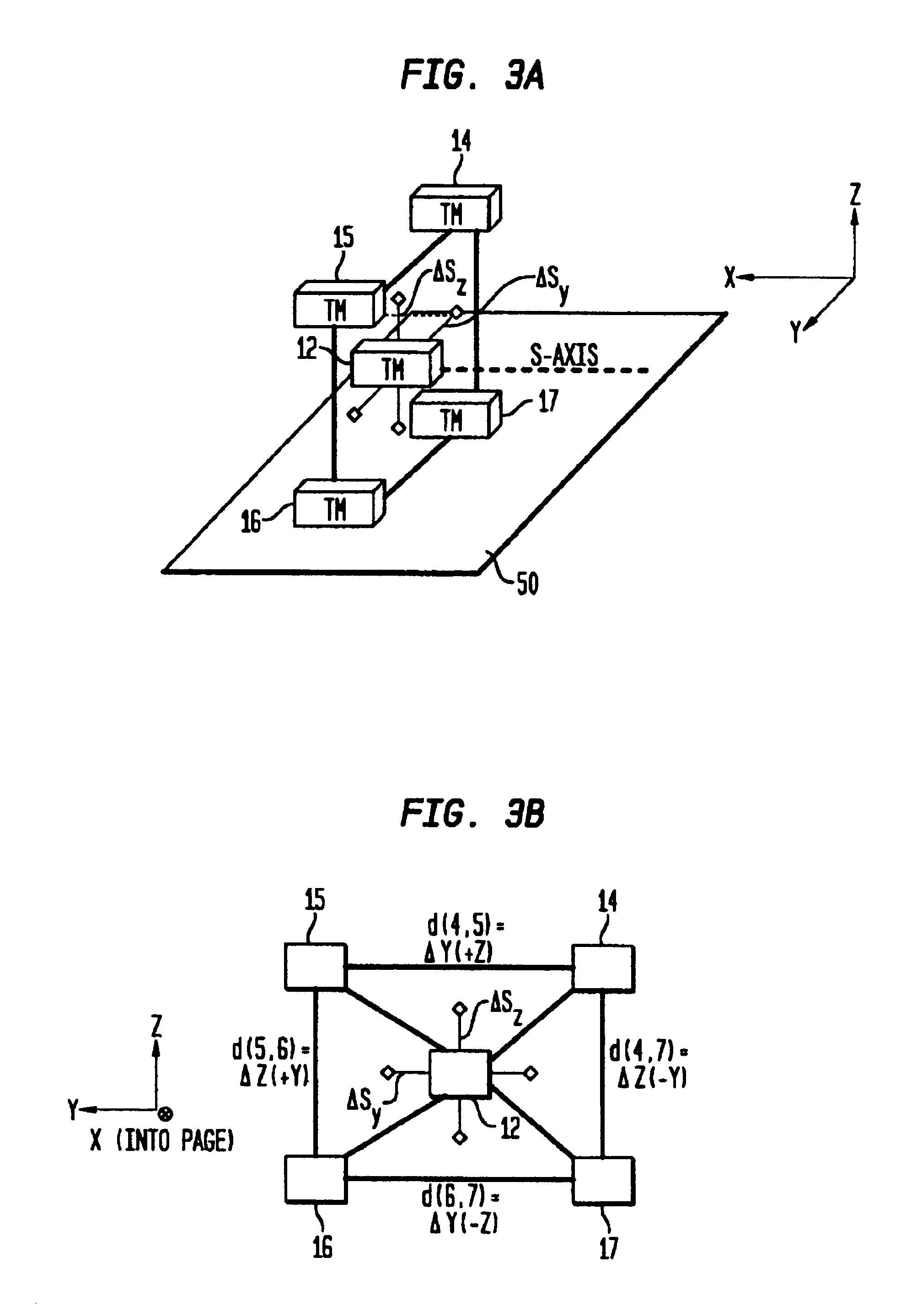
A magnetic anomaly sensing system uses triaxial magnetometer (TM) sensors arranged in a three-dimensional array. A processor coupled to the TM sensors generates partial gradient contraction data, and complete gradient tensor data and corresponding complete gradient contraction data. The generated data can be used to align the three-dimensional array with a magnetic target. Once the three-dimensional array is aligned with the magnetic target, the generated data can be used to uniquely determine (i) distance to the magnetic target, (ii) position of the magnetic target relative to the three-dimensional array, and (iii) the magnetic dipole moment of the magnetic target.

Description

FIELD OF THE INVENTIONThe invention relates generally to magnetic sensing systems, and more particularly to a magnetic anomaly sensing system that can be used to detect a magnetic object, unambiguously localize the magnetic object, and classify the magnetic object through the unambiguous measurement of the object's magnetic moment.BACKGROUND OF THE INVENTIONIn principle, magnetic sensing technologies can be used by divers or autonomous underwater sensing platforms (e.g., Autonomous Unmanned Vehicles (AUVs)) for detection, localization and classification (DLC) of magnetic objects. For example, underwater mines in littoral “very shallow water / surf zone” (VSW / SZ) environments constitute magnetic objects that may be located in the sea bottom, tethered at mid depth or floating at the surface. Therefore, fully autonomous magnetic DLC of all underwater mines requires magnetic sensing systems that will function effectively onboard highly-mobile sensing platforms such as free-swimming divers...

Claims


Application Information

Patent Timeline
Patent Type & Authority Patents(United States)
IPC IPC(8): G01V3/15
CPCG01V3/15
Inventor WIEGERT, ROY F.
Owner THE UNITED STATES OF AMERICA AS REPRESENTED BY THE SECRETARY OF THE NAVY
Why Eureka
Eureka Blog
Learn More