
Systems and methods for controlling brightness of an avionics display

a technology for avionics displays and brightness, applied in the direction of electric variable regulation, process and machine control, instruments, etc., can solve the problems of affecting the amount of backlight generated, affecting and the use of fluorescent bulbs for dimmable backlighting, so as to achieve wide dimming range and adverse effect on the readability of the avionics display

Inactive Publication Date: 2005-01-11
GARMIN AT
View PDF29 Cites 359 Cited by
  • Summary
  • Abstract
  • Description
  • Claims
  • Application Information

AI Technical Summary

Benefits of technology

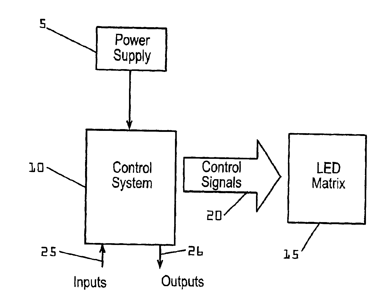
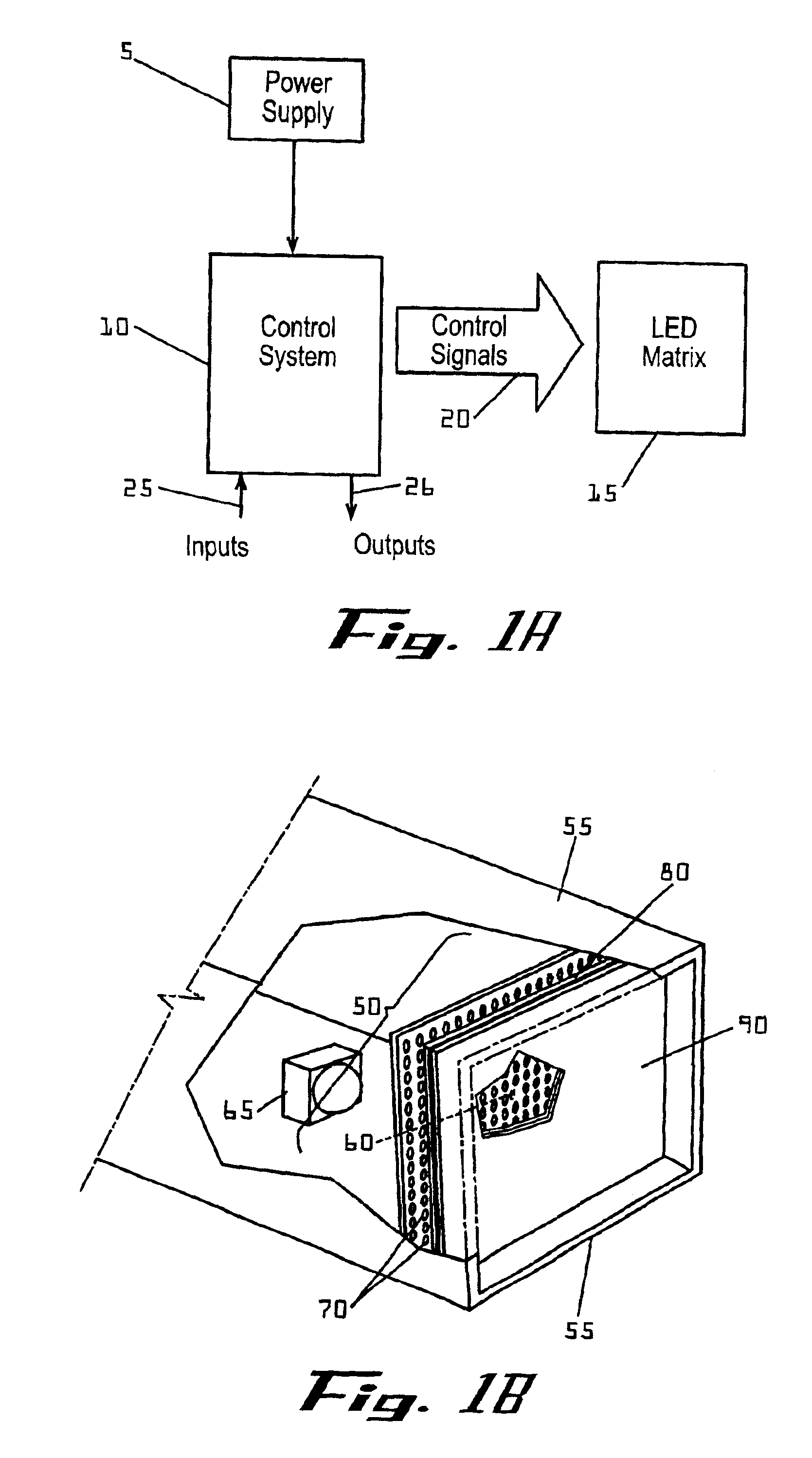
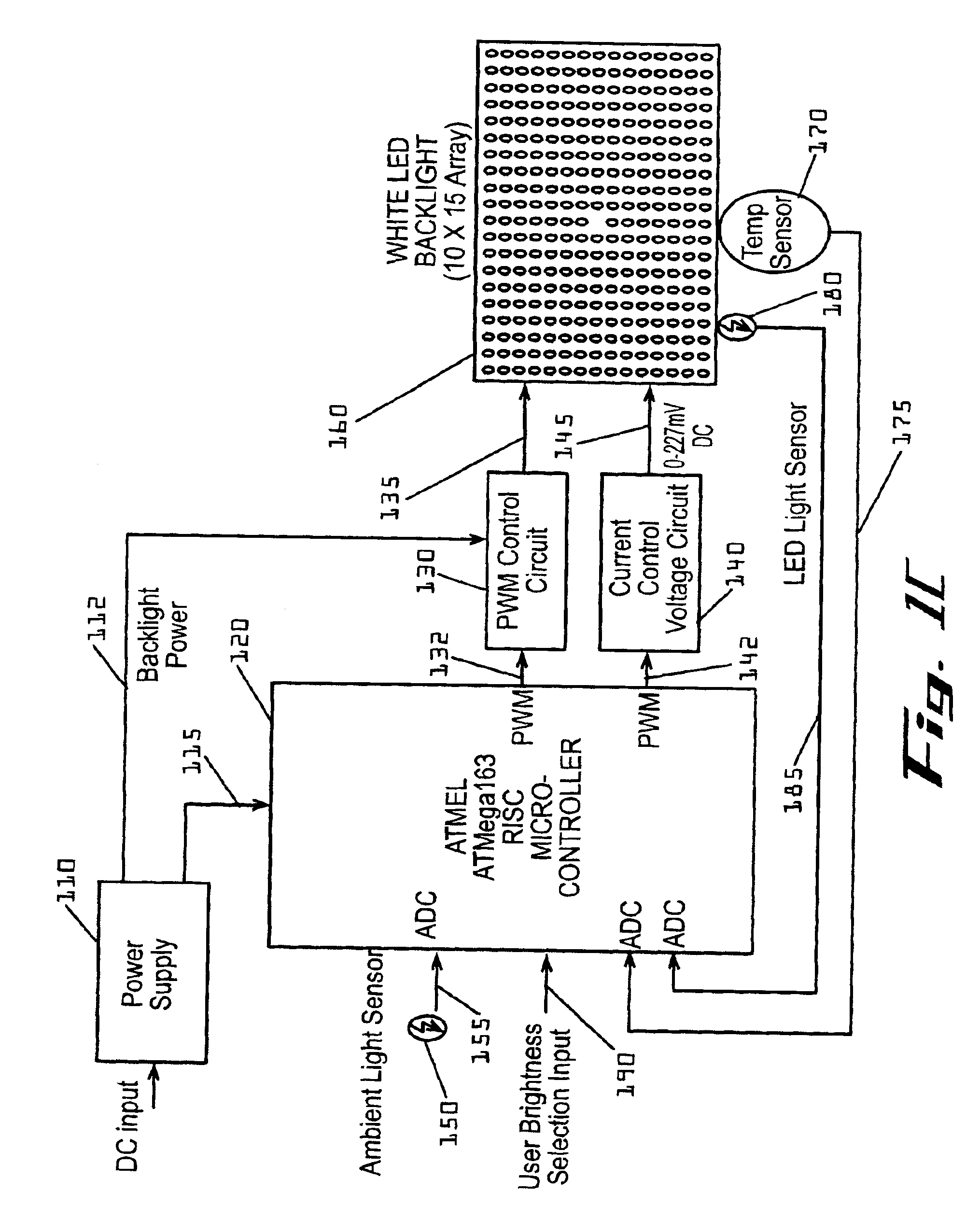
The present invention provides for systems and methods for dimming a Light-Emitting-Diode (LED) matrix functioning as a backlight to an avionics display. A control unit receives inputs, for example, including signals indicating light levels generated by a backlight, and calculates appropriate output signals that are provided to a display unit comprising a plurality of LEDs allowing a wide range of dimming. A plurality of LEDs provide redundant light sources such that the failure of a single LED does not adversely effect readability of the avionics display.

Problems solved by technology

Age of the components is another factor impacting the amount of light generated by the backlight.
However, use of fluorescent bulbs for dimmable backlighting presents several undesirable characteristics.
First, fluorescent bulbs have a finite life and are prone to sudden failures.
The failure of a single bulb may render the display unreadable and replacing bulbs constitutes an unscheduled maintenance action which can adversely impact flight schedules.
This is undesirable for several reasons, a few of which are as follows.
First, a high voltage requires a dedicated high voltage power source adding to the complexity and weight of the airplane.
Second, high voltages increase the risk of sparks due to malfunctions, such as a short circuit, presenting a potential danger.
Third, electrical circuitry controlling high voltage is prone to high frequency signal generation (i.e., electrical ‘noise’) which can interfere with the operation of other electrical aircraft systems.

Method used


Image

  • Systems and methods for controlling brightness of an avionics display
  • Systems and methods for controlling brightness of an avionics display
  • Systems and methods for controlling brightness of an avionics display

Examples


Embodiment Construction

The present invention now will be described more fully hereinafter with reference to the accompanying drawings, in which preferred embodiments of the invention are shown. This invention may, however, be embodied in many different forms and should not be construed as limited to the embodiments set forth herein; rather, these embodiments are provided for thoroughness and completeness, and fully convey the scope of the invention to those skilled in the art. Like numbers refer to like elements throughout.

Many modifications and other embodiments of the invention will come to mind to one skilled in the art to which this invention pertains having the benefit of the teachings presented in the foregoing descriptions and the associated drawings. Therefore, it is to be understood that the invention is not to be limited to the specific embodiments disclosed and that modifications and other embodiments are intended to be included within the scope of the appended claims. Although specific terms a...


PUM


Abstract

The present invention provides for systems and methods for dimming a LED matrix functioning as a backlight to an avionics display. A system according to an embodiment of the present invention comprises a processor for receiving inputs of ambient lighting and temperature, as well as light generated by the LED matrix. The processor provides modulated pulse wave signals (square waves) to two control circuits for controlling the LED matrix in two modes. At low dimming levels, the processor modulates the duty cycle of a first square wave for affecting the light level and maintains a minimal duty cycle of a second square wave. Once the highest light level is obtained by increasing the duty cycle of the first square wave, the processor then modulates a second square wave by increasing its duty cycle. The duty cycle of the second square wave is modified by a circuit to produce a voltage level which is provided as an input to control light level of the LED matrix. As the duty cycle of the second signal is increased, so is the voltage level provided to the LED matrix and the light generated by the LED matrix.

Description

FIELD OF THE INVENTIONThe invention generally relates to controlling the brightness of an avionics display.BACKGROUND OF THE INVENTIONAvionics displays provide critical flight information to aircraft pilots. It is expected that such displays are readable under a variety of lighting conditions. At one extreme, displays must be readable in fall daylight conditions as well as at the other extreme, in complete darkness. Sudden changes in the interior cockpit lighting conditions may occur, such as when the general cockpit lighting is turned on or off or when clouds block direct sunlight. An appropriate amount of backlight illumination is required to ensure consistent, readable avionics displays under a variety of changing lighting conditions.Providing an appropriate amount of backlight requires a broad range of illumination. In dark ambient light conditions, low levels of backlight may be appropriate, such as 0.1 fL (foot Lamberts), whereas as in bright ambient light conditions, greater ...

Claims


Application Information

Patent Timeline
Patent Type & Authority Patents(United States)
IPC IPC(8): G09G3/34G09G3/14G09G3/04G09G3/32H05B33/02H05B33/08
CPCG09G3/14G09G3/32G09G3/3406H05B33/0854H05B33/0851G09G2320/029G09G2320/043G09G2320/0633G09G2320/064G09G2360/144G09G2360/145G09G2320/0626H05B45/12H05B45/18
Inventor BERG-JOHANSEN, ROAR
Owner GARMIN AT
Learn More