
Paper sheet stamp apparatus

Inactive Publication Date: 2005-01-11
KK TOSHIBA
View PDF22 Cites 1 Cited by
  • Summary
  • Abstract
  • Description
  • Claims
  • Application Information

AI Technical Summary

Benefits of technology

The present invention has been developed in consideration of the above-described respects, and an object thereof is to provide a paper sheet stamp apparatus which can securely and clearly stamp a surface predetermined position of a paper sheet conveyed at a relatively high speed.

Problems solved by technology

It has therefore been difficult to rotate the stamp hub at the same peripheral speed as the conveying speed of the mail matter and to rotate the stamp hub at an appropriate timing.
Therefore, when the letterpress of the stamp hub is pressed on the postage stamp portion of the mail matter, a speed difference is generated between the letterpress and mail matter.
There is a problem that the postmark warps or deviates.

Method used


Image

  • Paper sheet stamp apparatus
  • Paper sheet stamp apparatus
  • Paper sheet stamp apparatus

Examples


Embodiment Construction

Embodiments of the present invention will be described hereinafter in detail with reference to the drawings.

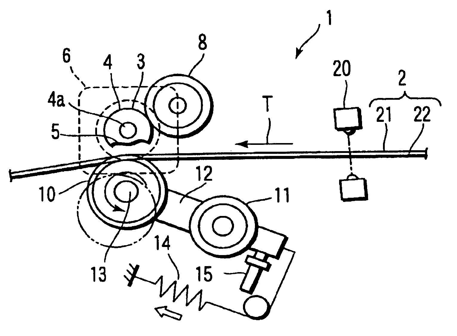
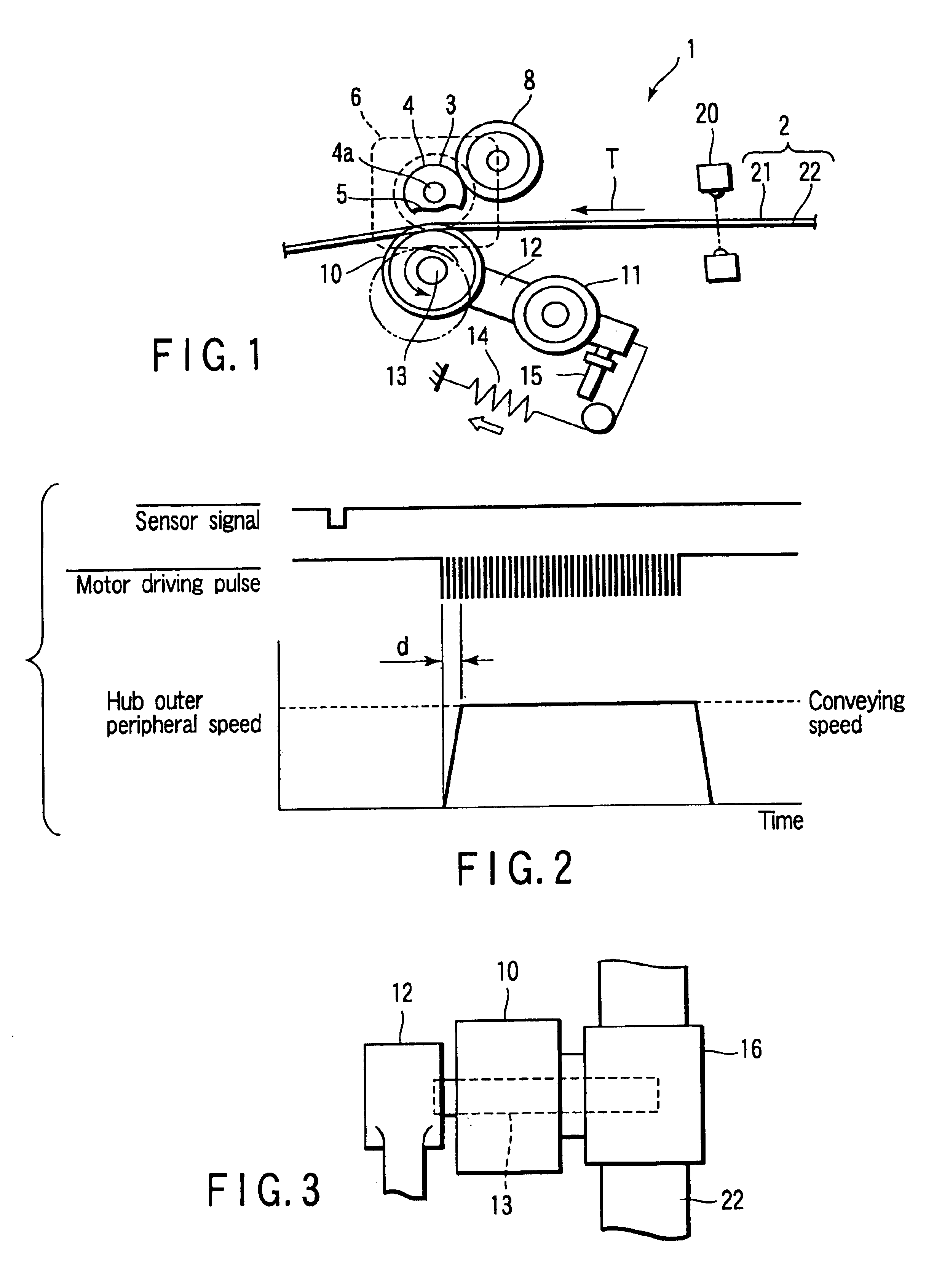
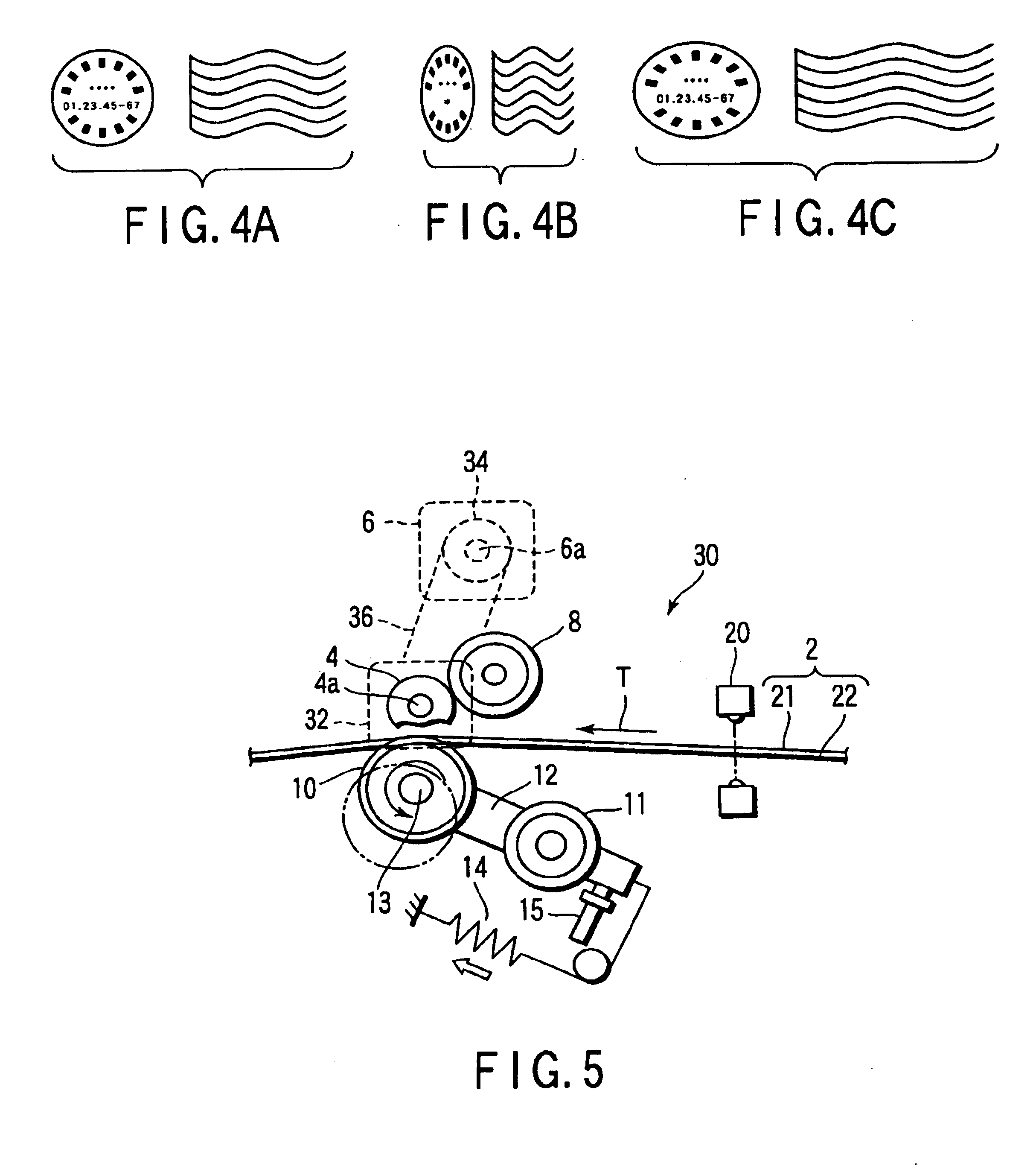
FIG. 1 shows a schematic structure of a stamp apparatus 1 (paper sheet stamp apparatus) according to a first embodiment of the present invention. Here, the stamp apparatus 1 will be described for stamping a portion of a mail matter conveyed at a relatively high speed (3.8 m / s in the present embodiment), to which a postage stamp is attached (hereinafter referred to simply as the postage stamp portion), with a postmark.

The stamp apparatus 1 includes a conveying belt pair 2 (conveying mechanism) which runs in an arrow T direction in the drawing at a constant speed in a holding / binding state of the mail matter. In further detail, the conveying belt pair 2 includes: a conveying belt 21 extended to be brought in a face contact with the surface (first surface) on a side to which the postage stamp is attached; and a conveying belt 22 disposed opposite to the conveying belt 21 via a co...


PUM


Abstract

A stamp apparatus having a conveying belt pair for conveying a mail matter in an arrow T direction, sensor for detecting the conveyed mail matter, a stamp hub which roll-contacts a postage stamp portion of the mail matter, rotates, and stamps the portion with a postmark, and a backup roller for pressing the conveyed mail matter onto the stamp hub. The stamp hub is directly connected to the AC servo motor, and is rotated at a speed equal to a conveying speed of the mail matter, when a effective region contacts the mail matter.

Description

CROSS-REFERENCE TO RELATED APPLICATIONSThis application is based upon and claims the benefit of priority from prior Japanese Patent Application No. 2002-138514, filed May 14, 2002.BACKGROUND OF THE INVENTION1. Field of the InventionThe present invention relates to a paper sheet stamp apparatus which stamps the surface of a paper sheet conveyed at a constant speed.2. Description of the Related ArtPaper sheet stamp apparatuses have heretofore been known such as a stamp apparatus for stamping a portion of a mail matter conveyed at a high speed, to which a postage stamp is attached, with a postmark.This type of the stamp apparatus includes: a conveying belt pair running at a constant speed in a holding state of the opposite surfaces of the mail matter; a stamp hub for stamping a postage stamp portion of the conveyed mail matter with the postmark; and a backup roller rotatably disposed opposite to the stamp hub on a back-surface side of the mail matter. The backup roller presses the mail...

Claims


Application Information

Patent Timeline
IPC IPC(8): G07B17/00B41K3/14B41K3/50B41K3/60B41K3/64B65H5/02
CPCG07B17/00508G07B17/00661G07B2017/00693G07B2017/00556G07B2017/00548B41K3/44
Inventor ITOH, SHINICHIASARI, YUKIO
Owner KK TOSHIBA
Learn More