Orbiting blade coaxial cable cutter/stripper

a coaxial cable cutter and cutting blade technology, applied in the direction of electrical cable installation, apparatus for removing/armouring cables, electrical equipment, etc., can solve the problems of deteriorating the centering accuracy and achieve the effect of improving the stripping function

Inactive Publication Date: 2005-01-11
ORBITAL TECH
View PDF8 Cites 3 Cited by
  • Summary
  • Abstract
  • Description
  • Claims
  • Application Information

AI Technical Summary

Benefits of technology

At what is considered the front end of the apparatus, a pair of clamping jaws are mounted for movement toward and away from one another to fix the axial position of the workpiece during the cutting and stripping operations. Each jaw incorporates a toothed rack engaged with a single pinion gear on the output shaft of a DC motor. The jaws are driven linearly by the motor along a common central axis, providing a simple and reliable mechanical arrangement with a minimum of parts. The motor is controlled by drive electronics which digitally control current through the motor (motor torque) and hence the clamping force. A unique software feature increases the clamping force during the stripping operation, when axial movement of the workpiece is most likely to occur, and returns to the lower value for other functions. The higher and lower clamping forces are user programmable, permitting use of the clamping mechanism with appropriate clamping force over a wide range of cable sizes and other conditions. The mechanism also incorporates novel and improved means for adjusting the horizontal centering position of the jaws.
The mounting and motion assembly for the cutting blade includes three plates, namely, a rear plate rigidly connected to the support upon which the blade is mounted, a stationary, center plate, and a front plate. The front plate is connected through horizontally disposed, linear, roller bearings to the center plate for horizontal movement relative thereto. The rear plate is connected, through an opening in the center plate, to the front plate by vertically disposed, linear, roller bearings for vertical movement of the rear plate upon the front plate. Thus, the rear plate is simultaneously movable both vertically (upon the front plate) and horizontally (with the front plate) to provide the desired orbital motion of the blade. The linear bearings are preloaded by adjustment screws, essentially eliminating all play from movement of the plates.
A pair of so-called gripper members are positioned on horizontally opposite sides of the cable near the plane of the blade cutting edge. Each gripper member includes an arm with an edge portion. Respective stepper motors move the edge portions toward and away from one another at equal distances from the axis of the cable. The user may program the device to actuate the stepper motors to move the arms inwardly until the edge portions engage the outermost layer of the cable either before or after the blade has been moved to sever the layer. Engagement of the edge portions of the gripper members reduces the tendency of the portion of the cable extending past the blade to “whip” during the cutting operation. In any case, after the slug is severed from the remainder of the outermost layer of the cable, engagement of the gripper members with the slug, coupled with rearward movement of the carriages, causes the slug to be stripped from the cable and fall by gravity to a disposal position clear of any moving parts of the apparatus. Furthermore, the slug is also engaged by the blade, resulting in three-point contact (the blade and the edge portions of the two gripper member arms) with the slug for enhanced stripping action.

Problems solved by technology

In order to avoid excessive generation of heat from friction between guide and workpiece and resulting expansion of the workpiece, it was necessary to provide an appreciable clearance with consequent degradation of centering accuracy.

Method used


Image

  • Orbiting blade coaxial cable cutter/stripper
  • Orbiting blade coaxial cable cutter/stripper
  • Orbiting blade coaxial cable cutter/stripper

Examples


Embodiment Construction

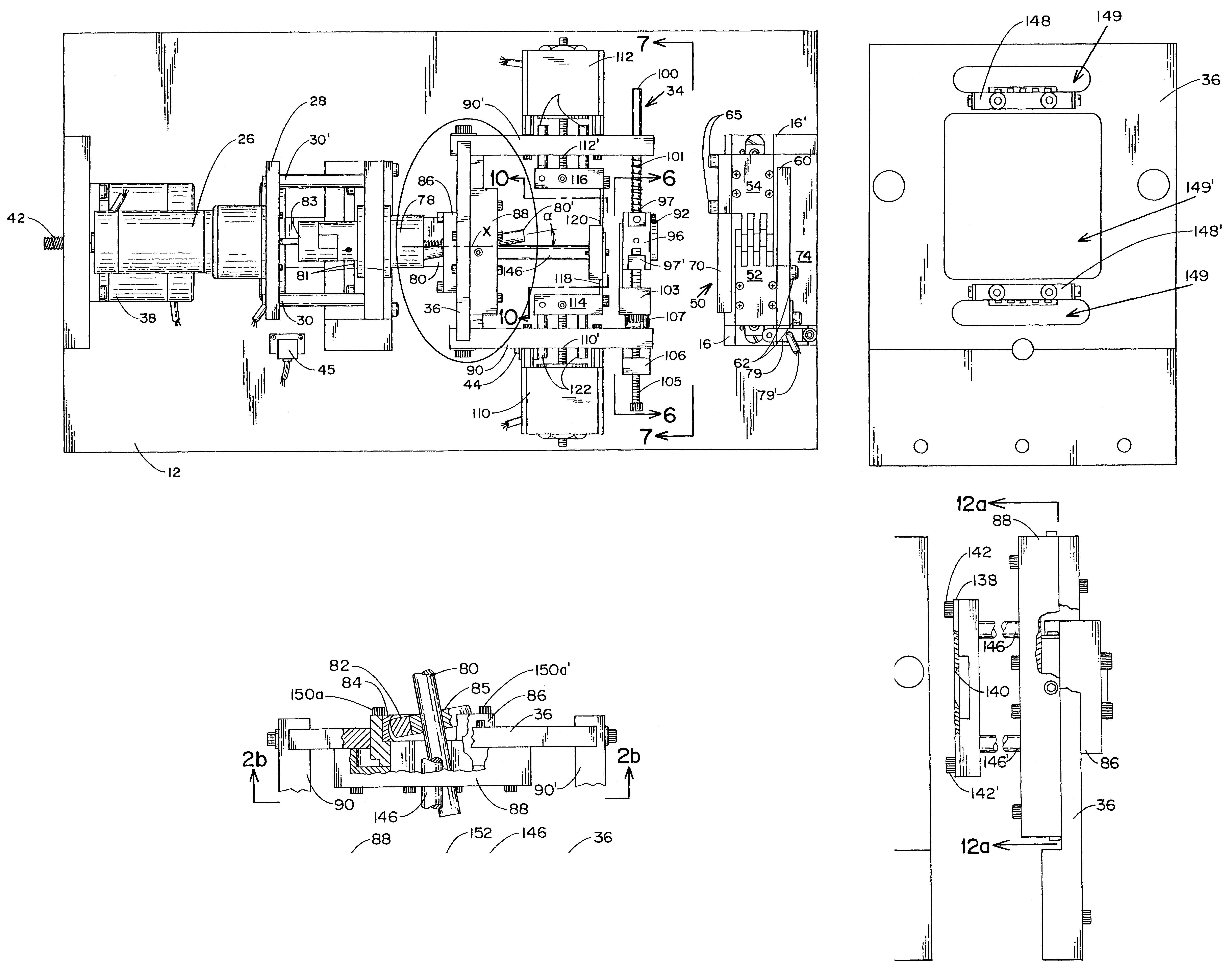
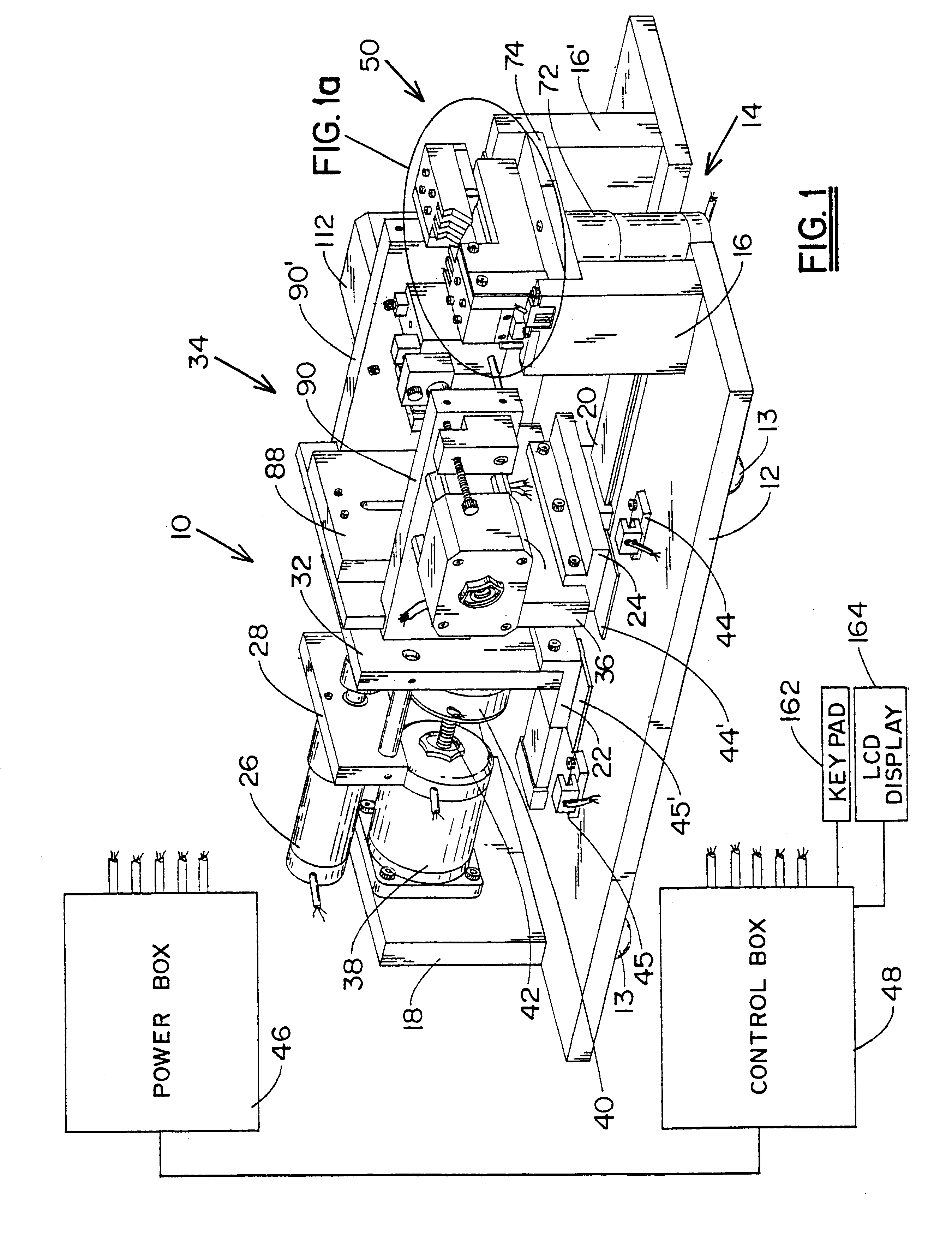
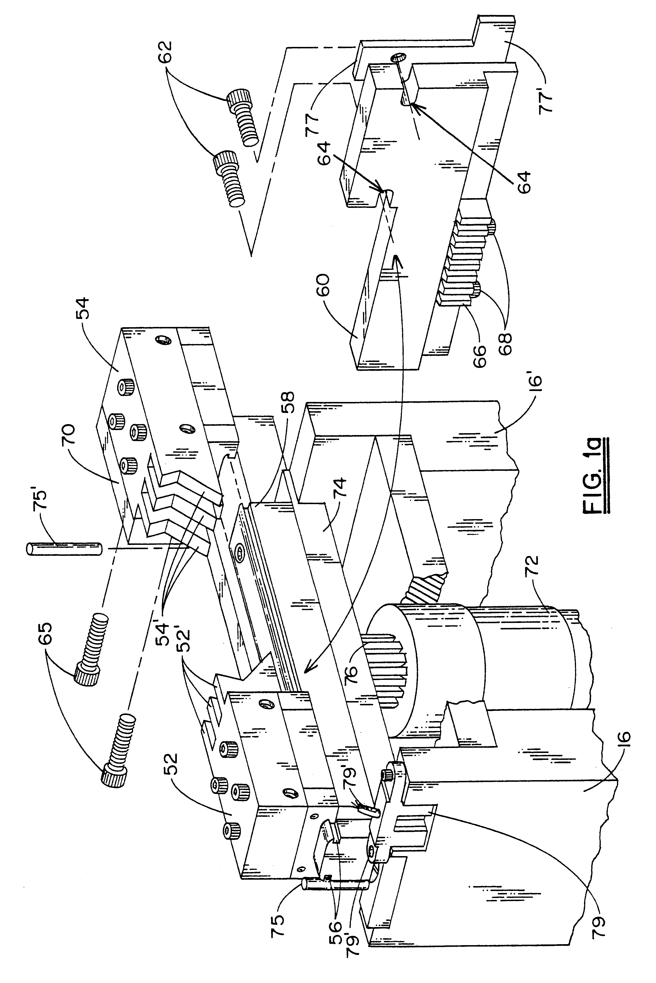
The apparatus of the invention, in the illustrated embodiment, is denoted generally by reference numeral 10. Apparatus 10 would, of course, be enclosed in an appropriate housing to prevent manual contact with moving parts, provide for insertion and withdrawal of workpieces, scrap removal, etc. However, since the design of the housing plays no part in the present invention, it is omitted from the drawings. The fixed frame of the apparatus includes horizontal plate 12, resting on feet 13 and having open, cutout area 14 at what is considered the front end of the apparatus, front, vertical supports 16, 16′ on opposite sides of open area 14, and rear, vertical support 18. Guide ways 20 are fixedly attached to the upper surface of plate 12 for sliding engagement by first and second carriages 22 and 24, respectively. For optimum rigidity and stability, the carriages are mounted to the ways via recirculating, linear, ball bearings pre-loaded to essentially remove play. DC motor 26 is mounte...


PUM

PropertyMeasurementUnit
Resilienceaaaaaaaaaa

Abstract

Apparatus for supporting a coaxial cable, or the like, and effecting cutting and stripping operations to remove a portion of one or more layers which concentrically cover a central conductor. A single blade, having a circular cutting edge, is moved in an orbital path about the cable with rotary motion of a motor translated to orbital motion of the blade through a plurality of plates relatively movable on crossed, linear, roller bearings and a shaft eccentrically affixed to the motor with the shaft and motor axes at an acute angle to one another. The shaft extends through a spherical bearing mounted in one of the plates, thereby translating nutational motion of the shaft to orbiting motion of the plate which is directly attached to the blade. A unique clamping assembly includes a pair of jaws having respective gear racks engaging a single pinion gear on a motor output shaft for linear movement of the jaws by equal distances in opposite directions. A microprocessor controls the level of current to the motor, thereby adjusting the clamping force applied to the cable, and increases this force during the stripping operation, when maximum axial force is applied to the cable. A guide bushing establishes the radial position of the cable axis and is stationary during blade movement, thereby permitting the opening in the bushing to closely approximate the cable diameter. The position of the bushing is adjustable to align the central axis of the bushing opening with that of the blade cutting edge. The bushing is also movable to an inoperative position to permit unobstructed access to the blade for replacement thereof. A pair of gripping members are movable to engage the severed portion of the covering layer to assist in the stripping operation, and a unique combination of hardware and software is provided for calibrating the position of the gripping members at equal distances from the axis of the cable.

Description

BACKGROUND OF THE INVENTIONThe present invention relates to apparatus for severing multiple layers of coating or covering materials from a central core such as a conductor of a coaxial cable or an optical fiber. More specifically, the invention relates to improvements in automated machinery for sequentially severing and removing multiple layers of material from a wire or other filamentary member utilizing a cutting blade with a circular cutting edge which orbits the material being cut. The prior art includes many types of apparatus for severing and removing a covering layer from a central, filamentary member, as in the removal of insulation and sheathing from an electrical wire or coaxial cable. Such apparatus typically includes one or more cutter blades which are moved from a position spaced radially outwardly from the position at which the cut is to be made inwardly toward the wire, at least partially through the covering layer. The blade(s) may be moved only in linear, reciprocat...

Claims


Application Information

Patent Timeline
IPC IPC(8): H02G1/12
CPCH02G1/1265H02G1/127Y10S83/947Y10S83/924Y10T83/04Y10T83/8772Y10T83/8796
Inventor PALMOWSKI, DAVID J.
Owner ORBITAL TECH
Why Eureka
Try Eureka