
Motor integrated parallel hybrid transmission

Inactive Publication Date: 2005-01-04
TSAI LUNG WEN +1
View PDF31 Cites 39 Cited by
  • Summary
  • Abstract
  • Description
  • Claims
  • Application Information

AI Technical Summary

Benefits of technology

It is, therefore, an object of the present invention to provide a parallel hybrid transmission which avoids the disadvantages of the prior art.
It is yet another object of the present invention to provide a parallel hybrid transmission that enables selective operation of engine-only, motor-only, and combined engine and motor torque transmission to an output shaft.
It is even yet another object of the present invention to provide a parallel hybrid transmission exhibiting small mechanical and electrical losses.
It is still even yet another object of the present invention to provide a parallel hybrid transmission of reliable and simplified design over prior art transmissions.
Thus, the combination of the torque transfer devices and compound planetary gear train of the instant invention provide increased versatility of a hybrid vehicle transmission over prior art hybrid vehicle transmissions, while maintaining a simplified, reliable transmission construction operable through engine-only, motor-only, and combined engine and motor torque transmission to the transmission output shaft.

Problems solved by technology

As a result, the engine cannot run at its optimal operating condition most of the time which leads to poor fuel economy and emissions.
This problem is particularly important in large cities where stop-and-go driving is common and pollution is a major problem.
However, electric vehicles suffer the problems of limited driving range, typically around 200 miles, insufficient acceleration and hill climbing performance, and prolonged battery charging time.
Attempts have been made in the past to provide parallel hybrid electric vehicle transmissions, but with limited success.
This arrangement allows the electric motor to supplement the torque supplied by the heat engine to enable a two-degree-of-freedom transmission, but fails to enable engine-only or motor-only operation, thus limiting the utility of the transmission to one having two modes of forward driving operation.

Method used


Image

  • Motor integrated parallel hybrid transmission
  • Motor integrated parallel hybrid transmission

Examples


Embodiment Construction

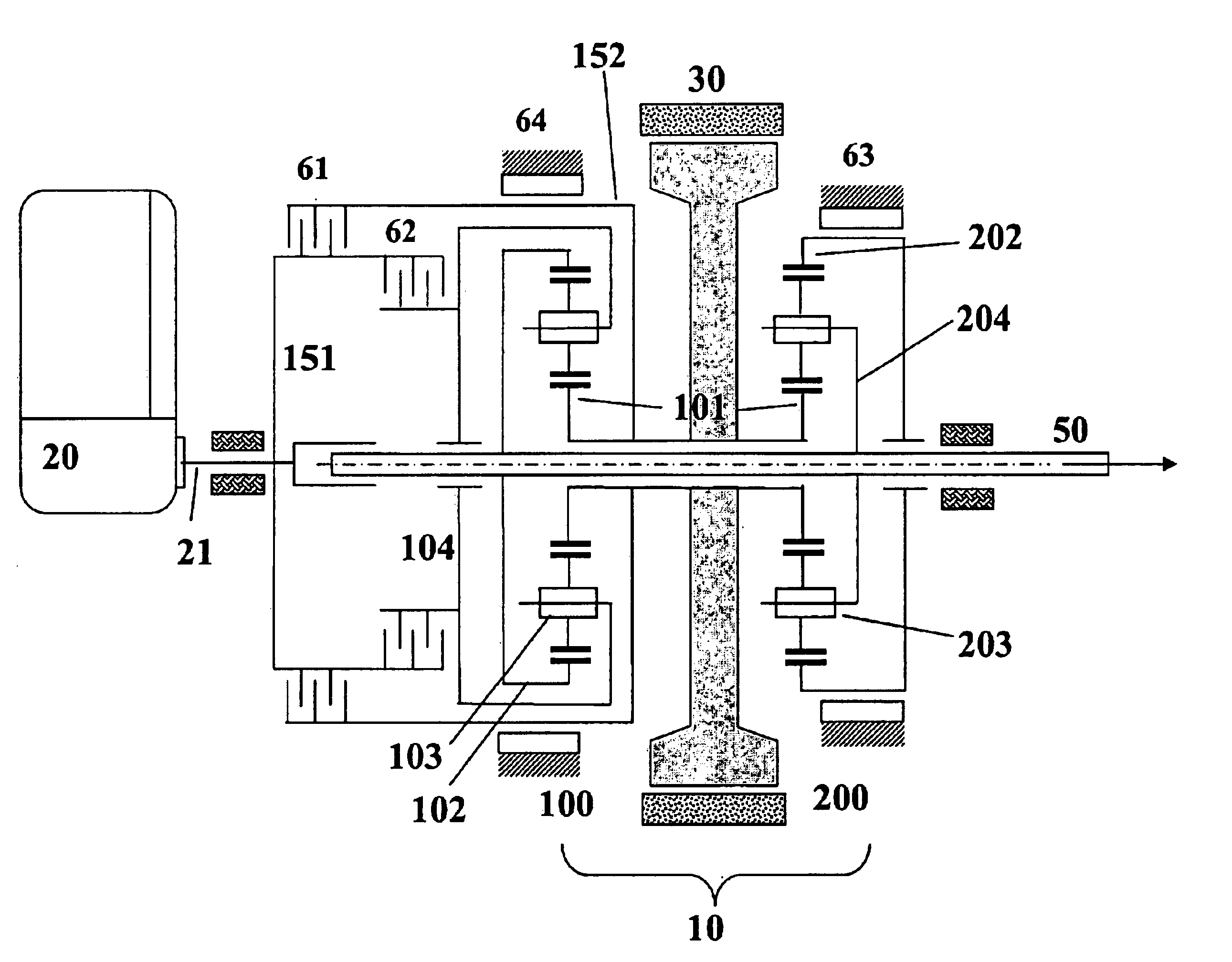
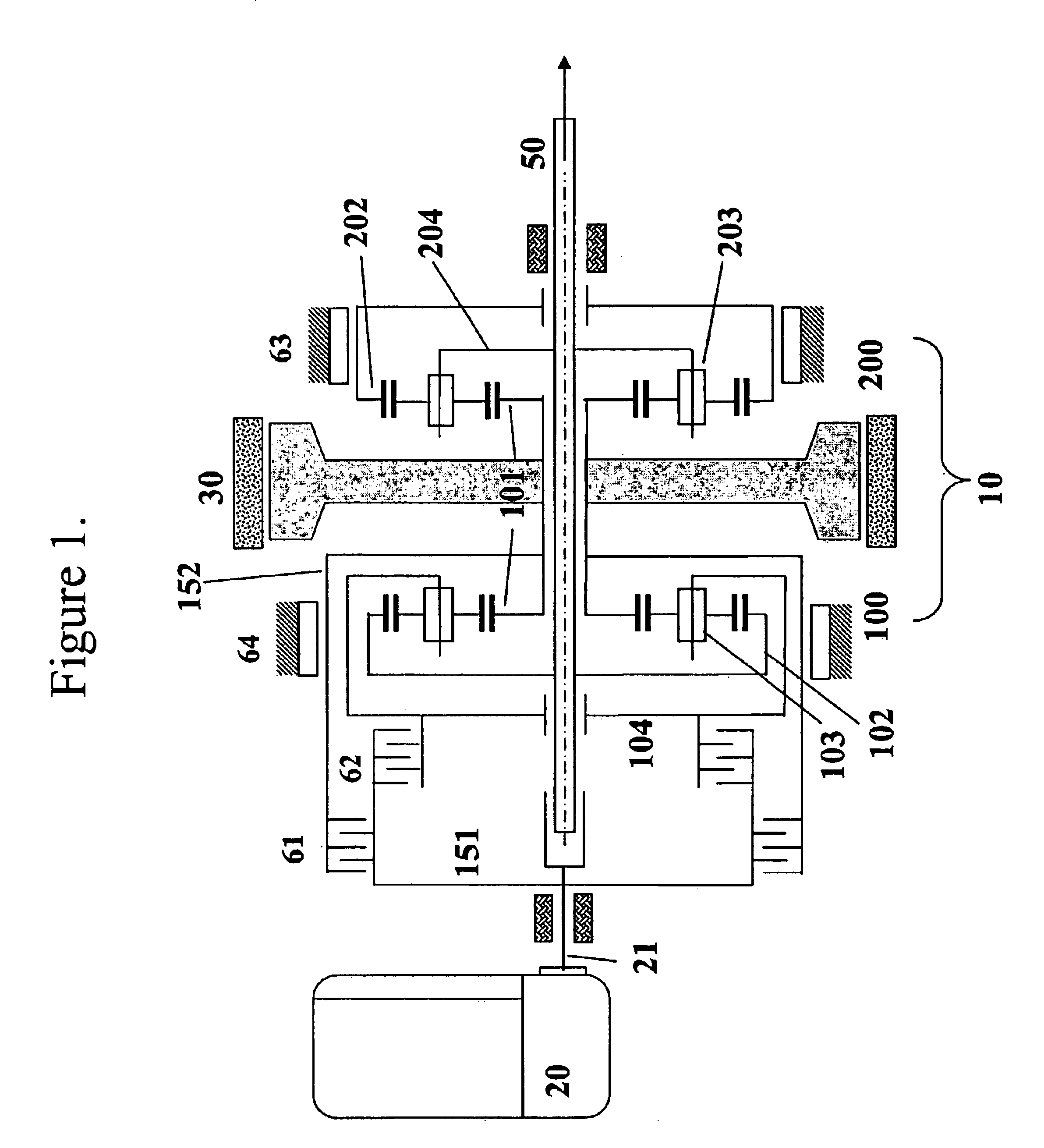
As shown in the schematic representation of FIG. 1, the parallel hybrid electric vehicle transmission of the instant invention comprises a compound planetary gear set (shown generally at 10), an engine 20, an engine input shaft 21, a combined electric motor and generator 30, an output shaft 50, and four torque transfer devices 61, 62, 63, and 64. Torque transfer devices 61 and 62 preferably comprise multi-disk clutches, and torque transfer devices 63 and 64 preferably comprise band clutches. However, other similarly configured torque transfer devices, such as one-way clutches, may likewise be used without departing from the spirit and scope of the instant invention.

Compound planetary gear set 10 more particularly comprises an input planetary gear train (shown generally at 100) and an output planetary gear train (shown generally at 200). Each of planetary gear trains 100 and 200 share a compound sun gear 101. Input planetary gear train 100 further comprises a ring gear 102 and a plur...


PUM


Abstract

A motor-integrated transmission mechanism for use in parallel hybrid electric vehicles. The transmission can provide five basic modes of operation that can be further classified into sixteen sub-modes: one electric motor mode, four engine modes, four engine / charge modes, three power modes and four regenerative braking modes. Each of these sub-modes can be grouped into like clutching conditions, providing the functional appearance of a conventional 4-speed automatic transmission, with electric launch, engine-only, engine / charge, power-assist, and regeneration capability. CVT capability is provided with one of the engine / charge modes. The transmission can be incorporated in front-wheel drive and in rear-wheel drive vehicles.

Description

BACKGROUND OF THE INVENTION1. Field of the InventionThe invention disclosed herein relates generally to parallel hybrid electric vehicle (HEV) transmissions, and more particularly to parallel hybrid electric vehicle transmissions capable of providing one- or two-degree-of-freedom operation in order to couple and transmit torque from two power sources to the drive wheels of the automobile, or to split the torque from one power source into two parts, one for driving the automobile and the other for charging the vehicle batteries.2. Description of the BackgroundInternal combustion engines are widely used for driving passenger cars. Typically, the size of an engine used in a vehicle is several times greater than the average power requirement of the vehicle in order to meet various operating conditions. As a result, the engine cannot run at its optimal operating condition most of the time which leads to poor fuel economy and emissions. This problem is particularly important in large citi...

Claims


Application Information

Patent Timeline
IPC IPC(8): B60K6/04B60K6/00F16H3/72F16H3/44B60K6/365B60K6/48B60W10/02B60W10/08B60W10/10
CPCB60K6/365B60K6/48B60W10/02B60W10/08B60W10/10F16H3/725Y02T10/6247Y02T10/6221Y10S903/945Y10S903/946Y10S903/91Y02T10/62
Inventor TSAI, LUNG-WENSCHULTZ, GREGORY A.
Owner TSAI LUNG WEN
Learn More