
Seat belt latch plate and method of making same

a latch plate and seat belt technology, applied in the field of latch plate, can solve problems such as unfavorable rattle or noise, and achieve the effect of reducing any rattle or noise that the latch plate could mak

Inactive Publication Date: 2005-01-04
GM GLOBAL TECH OPERATIONS LLC +1
View PDF26 Cites 28 Cited by
  • Summary
  • Abstract
  • Description
  • Claims
  • Application Information

AI Technical Summary

Benefits of technology

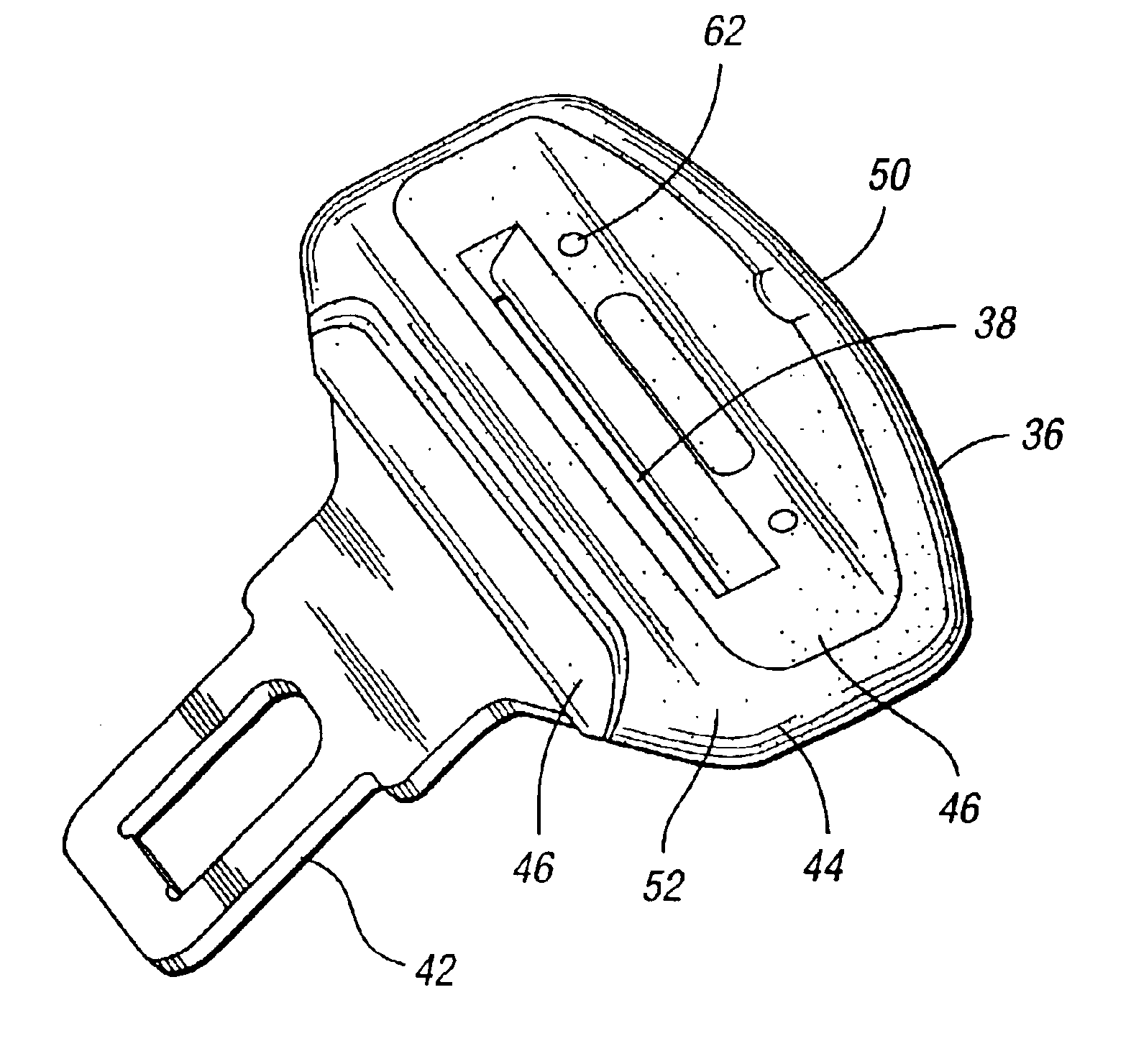
The seat belt latch plate is produced from a plated metal stamping that has a portion of it over molded with a polypropylene coating. This portion has a slot for pass-through of the seat belt webbing. The slot allows the free travel of the latch plate as the seat occupant draws the latch plate along the webbing to fasten and wear the seat belt.
Accordingly, the invention is a slotted latch plate for a vehicle seat belt system which has webbing extending through the slot as the latch plate is moved by the seat back in potentially noise-making respect to the C-pillar trim. The latch plate has a relatively hard plastic coating over molded on the latch plate where the latch plate slot receives the webbing. The latch plate also has a relatively soft plastic surround over molded on at least a portion of the relatively hard plastic coating in cooperation therewith and sufficiently thick that any noise made by the latch plate imparted by movement of the seatback and / or vehicle vibrations is reduced.
The invention is also a method of making a potentially noise-proof latch plate for a vehicle seat belt system. The method provides a plated steel stamping. A relatively warm coating of a relatively hard plastic is injection molded onto the exterior of the stamping. Then, a relatively soft plastic is injection molded onto selected portions of the relatively hard plastic while the hard plastic coating is still warm and to a sufficient thickness that any rattle noise potentially made by the latch plate is reduced.

Problems solved by technology

Under certain road conditions, vibration or movement of the seatback and / or vehicle vibrations may shake the latch plate and / or the latch plate may swing (like a pendulum) and contact the C-pillar trim.
If the latch plate is next to the vehicle trim at the C-pillar, this shaking may cause undesirable rattle or noise.

Method used


Image

  • Seat belt latch plate and method of making same
  • Seat belt latch plate and method of making same
  • Seat belt latch plate and method of making same

Examples


Embodiment Construction

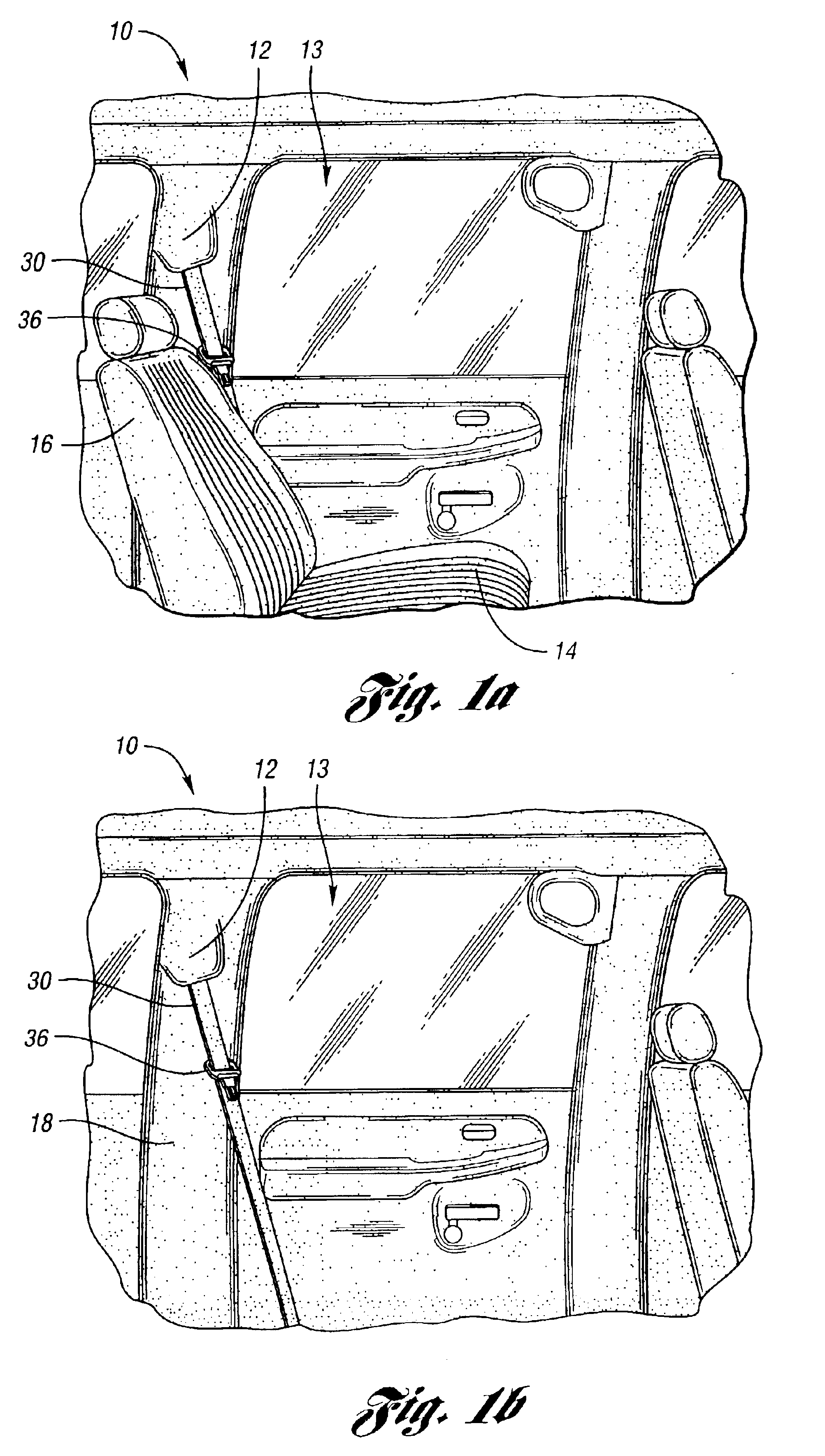
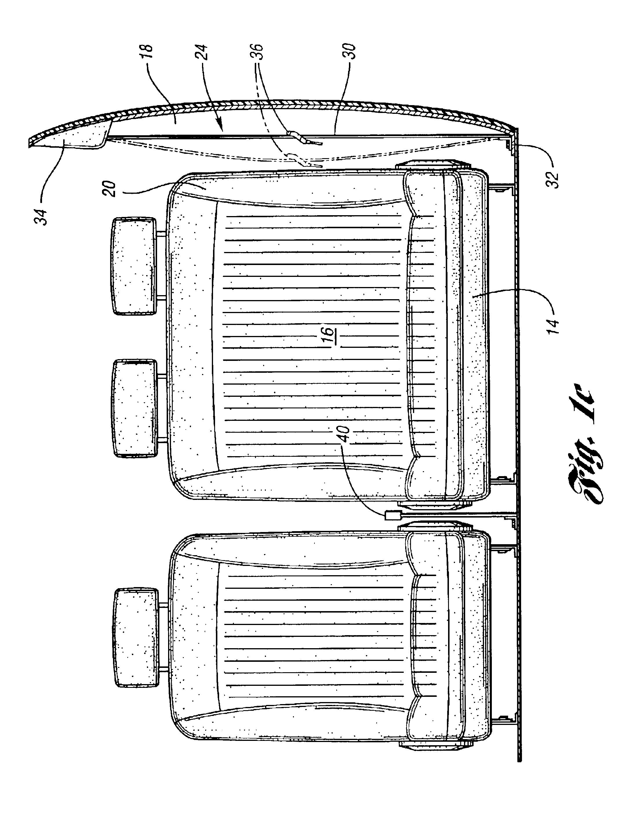
FIGS. 1a-c show an automotive vehicle 10 having a structural C-pillar portion 12 at the left rear quarter of the vehicle. The vehicle door 13 is substantially alongside a rear passenger seat 14 and seat back 16 having a seat back bolster 20. The door 13 is flanked on one side by a relatively hard polypropylene C-pillar trim panel 18. The right side of the rear seat at the C-pillar is essentially the mirror image of the left.

Vehicle 10 has a passenger safety seat belt system 24 for the left side passenger seat 14, 16. A similar seat belt system (not shown) is provided for the seat on the right side of the vehicle. The seat belt system includes a webbing 30 anchored at 32 to the vehicle body and is biasingly retracted into a retractor 34 as shown in FIG. 1c. The webbing is free to move inboard (FIG. 1c, phantom line) and outboard (FIG. 1c, solid line) at the C-pillar, restrained only by the bias of retractor 34. The webbing freely supports a latch plate 36 formed of a plated metal sta...


PUM


Abstract

An improved latch plate for a seat belt attached to a vehicle C-pillar. The latch plate is produced from a plated metal stamping that has a portion over molded with a hard polypropylene coating. This portion has a slot for pass through of the seat belt webbing that allows free travel of the latch plate in order for the seat occupant to fasten and wear the belt. A surround of soft Santoprene® 221-55 is over molded over the polypropylene coating for sound reduction.

Description

BACKGROUND OF THE INVENTION1. Field of the InventionThis invention relates to a slotted latch plate on the webbing of a vehicle seat belt.2. Description of the Related ArtAutomotive vehicles have a seat belt system to protect the driver and passenger. The seat belt in such systems is generally webbing which may be drawn across the lap and chest and latched as a restraint for the driver and passenger. A latch plate moves freely along the webbing and has a polypropylene coating to protect the webbing where it goes through a slot in the latch plate and for cosmetic or appearance reasons. One seat belt location is the rear seat alongside the C-pillar of the vehicle. When there is no passenger in this seat, the webbing of the seat belt system lays idle alongside the C-pillar.Under certain road conditions, vibration or movement of the seatback and / or vehicle vibrations may shake the latch plate and / or the latch plate may swing (like a pendulum) and contact the C-pillar trim. Accordingly, ...

Claims


Application Information

Patent Timeline
Patent Type & Authority Patents(United States)
IPC IPC(8): A44B11/25B60R22/18
CPCB60R22/18A44B11/2561
Inventor MOSKALIK, MICHAEL P.VAN ROOYEN, PAUL M.GRIFFIN, GARY J.
Owner GM GLOBAL TECH OPERATIONS LLC
Learn More