
Plastic blow-molded panel with improved structural geometry

a technology of structural geometry and plastics, applied in the direction of manufacturing tools, transportation and packaging, other manufacturing equipment/tools, etc., can solve the problems of reducing the cost of articles, reducing load capacity, sagging, creeping and warpage, etc., and achieve the effect of minimizing material consumption and minimizing material consumption

Inactive Publication Date: 2004-12-07
RUBBERMAID
View PDF5 Cites 21 Cited by
  • Summary
  • Abstract
  • Description
  • Claims
  • Application Information

AI Technical Summary

Benefits of technology

The design effectively resists sagging and warpage under high loads, maintaining a lightweight and cost-effective structure with improved load capacity, as demonstrated by reduced deflection in panel structures E and F during load testing.

Problems solved by technology

However, current designs that are lightweight and are fabricated from a minimum of plastic material, thereby lowering the cost of the article, can suffer from the drawback of lower load capacity and may also suffer from sagging, creeping and warpage under high load conditions, especially when used as a horizontal shelf.
Specifically, heavy loads placed on a lightweight panel structure can cause creeping, sagging or warping due to the panel structure's ability to withstand the load due to the insufficient wall thickness and insufficient weight of the panel structure.
As a result, the panel structure can creep, sag or warp thereby interfering with the panel structures inability to interact with the other components of the system, namely the support components.
Further, lightweight blow-molded panel structures have been known to fail under typical higher load conditions thereby causing frustration to the user and possible damage to the goods stored thereon.
In an attempt to the increase the load capacity of plastic blow-molded panel structures, manufacturers have resorted to making the panel structures heavier, thereby adding wall thickness and using more material, thereby driving up the costs.
Using additional materials increases the cost and the weight which is not preferred.
Further, using additional bracket or bracing components adds to the complexity of the shelving systems which makes them difficult to assemble and results in additional competition with more complex metal or wooden shelving systems.

Method used


Image

  • Plastic blow-molded panel with improved structural geometry
  • Plastic blow-molded panel with improved structural geometry
  • Plastic blow-molded panel with improved structural geometry

Examples


Embodiment Construction

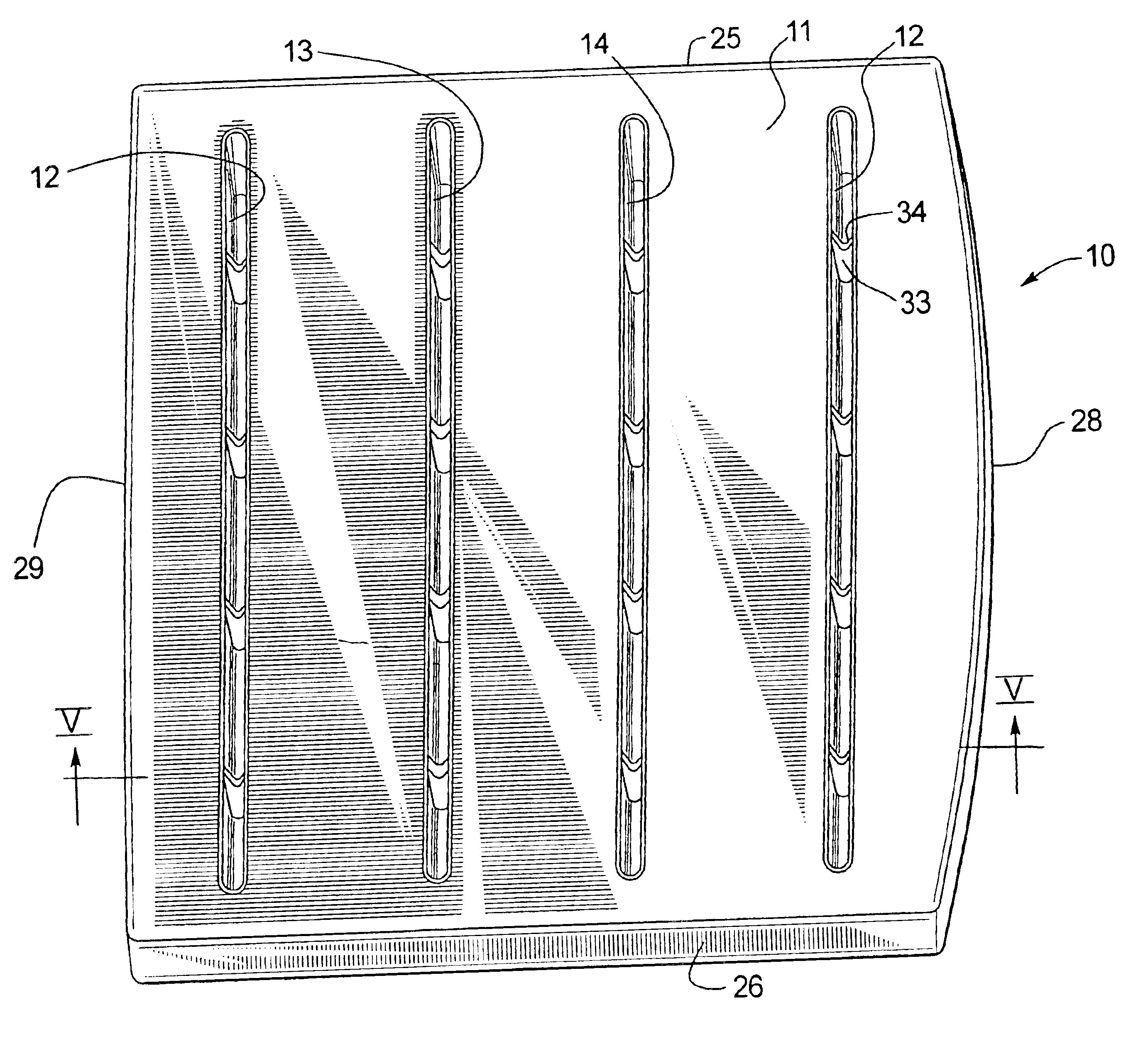
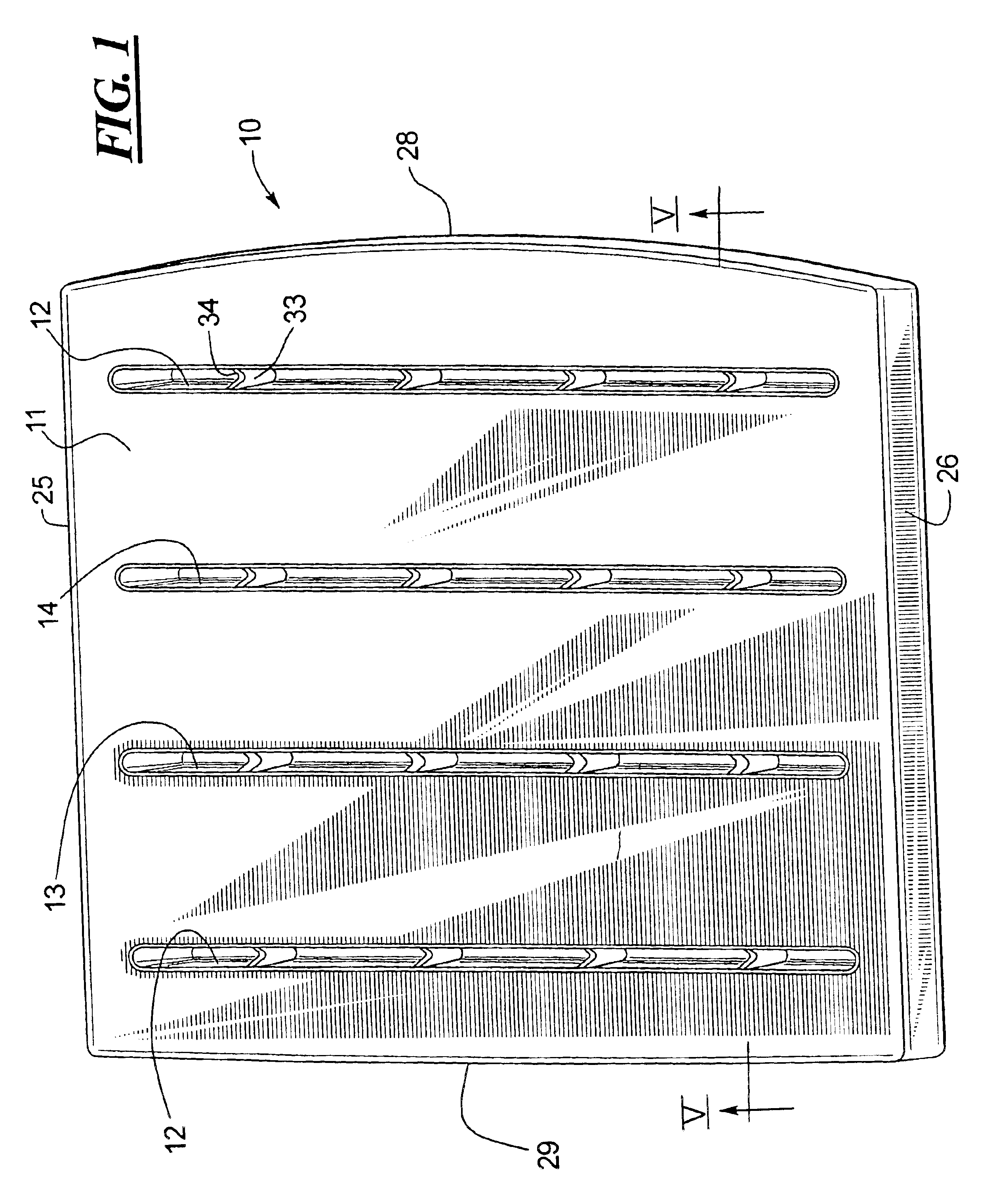
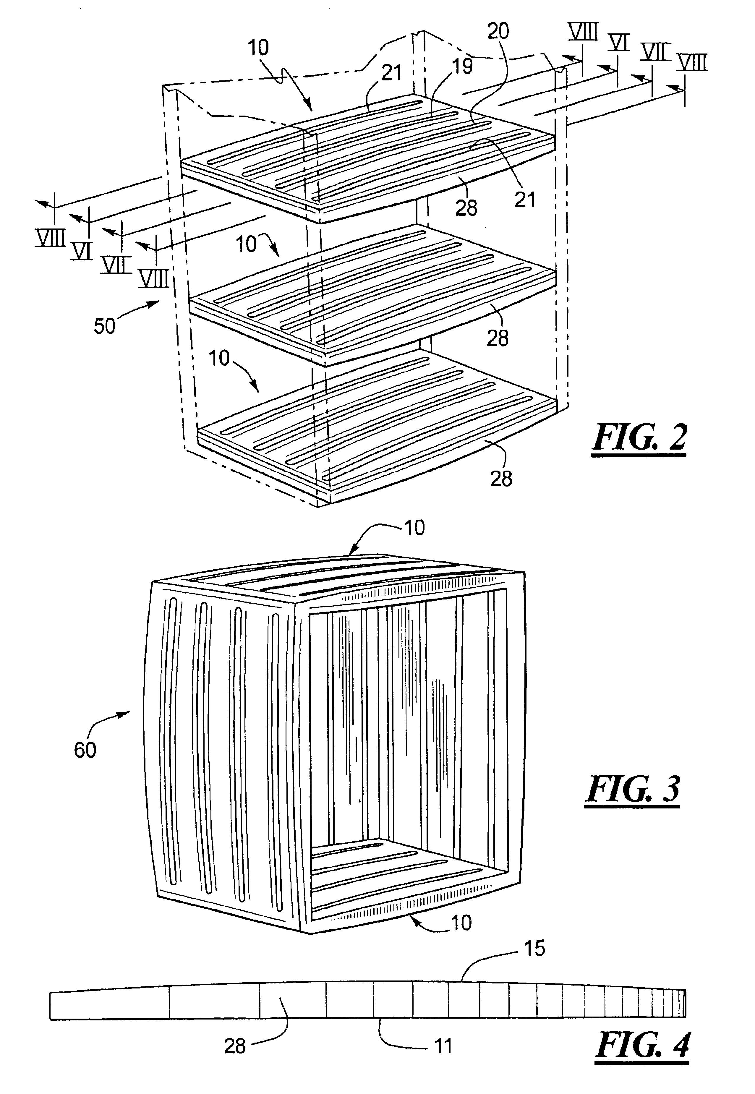
A bottom perspective view of a panel structure 10 made in accordance with this disclosure is illustrated in FIG. 1. A second panel 11 of the panel structure 10 includes a plurality of lateral slots which are shown at 12-14 in FIG. 1. Two lateral slots are shown at 12 because the geometry of these slots is substantially similar as discussed below. As shown in FIGS. 2 and 6-8, the slots 12-14 define a hollow lateral beam that extends outward from the second panel 11 to the first panel 15. In the embodiments illustrated, the lateral beams 12-14 are connected to the first panel 15 at the thickened areas shown at 16-18 in FIGS. 6-8. The thickened areas 16-18 are also defined by lateral grooves or slots 19-21 disposed in the first panel 15 as best seen in FIG. 2. The lateral beams defined by the slots 12-14 do not extend laterally all the way across the second panel 11, but, instead, stop short of the sidewalls shown at 25-26. FIGS. 6-8, and perhaps better in FIG. 4, also show that the fi...


PUM


Abstract

An improved plastic blow-molded panel structure is shown and described that is lightweight and provides superior resistance to sagging, warping and creeping under high stress loads, especially when used in a horizontal position. The disclosed panel structure includes a combination of transverse or lateral beams extending from the second panel towards the first panel and, in certain embodiments, a plurality of transverse ribs disposed within the lateral beams. The disclosed shelving units may be fabricated from conventional blow-molding processes.

Description

A plastic panel structure fabricated by way of a blow-molding process is shown and described. More specifically, a substantially hollow and lightweight blow-molded plastic panel structure is disclosed with a structural geometry that increases the load capacity of the panel structure and further resists creeping, sagging and warpage under high load conditions.BACKGROUND OF THE RELATED ARTPlastic panels and blow-molded panels are known in the art and may be combined with support structures to form a complete shelving or storage unit. The consumer appeal to plastic shelving systems includes two competing interests. Specifically, consumers prefer that the panel structures and shelving systems be lightweight but consumers also demand that the shelving systems be strong and durable or, in other words, have relatively high load capacities. Low cost is also a general concern.However, current designs that are lightweight and are fabricated from a minimum of plastic material, thereby lowering...

Claims


Application Information

Patent Timeline
Patent Type & Authority Patents(United States)
IPC IPC(8): E04C2/32
CPCE04C2/322Y10T428/2457Y10T428/24661Y10S108/901
Inventor SKOV, ERIK L.
Owner RUBBERMAID
Learn More