
Distriburted QoS policing system and method

a policing system and distributed technology, applied in the field of computer communication networks, can solve problems such as congestion, network devices are unable to keep up with an increase in traffic, and the network performance is affected

Inactive Publication Date: 2004-11-30
CISCO TECH INC
View PDF16 Cites 73 Cited by
  • Summary
  • Abstract
  • Description
  • Claims
  • Application Information

AI Technical Summary

Benefits of technology

It is an object of the present invention to provide different mechanisms to trigger export of information from a logic-module in order to provide flexibility of optimizing cost-accuracy tradeoff in policing traffic class or classes across a part or an entire network.
Various techniques are invented to trigger the export of information from the individual policers. This allows various means to reduce information exchanged between policers and increase the accuracy of policing. One technique may be superior to others in a given implementation in a given traffic condition.

Problems solved by technology

Congestion typically refers to the presence of too many packets in a subnet or a portion of a network, thereby degrading the network's performance.
Congestion occurs when the network devices are unable to keep up with an increase in traffic.
The upper layer applications may require global synchronization because of packets being dropped, which may significantly exacerbate the congestion problem.
There is a cost associated with the communication capacity used for exchanging such information.
If such "overhead" information is sent less often, it uses less of the capacity of the communication system, but it also decreases the accuracy of policing.
However, this patent does not disclose a policing of a class of traffic across an entire network.

Method used


Image

  • Distriburted QoS policing system and method
  • Distriburted QoS policing system and method
  • Distriburted QoS policing system and method

Examples


Embodiment Construction

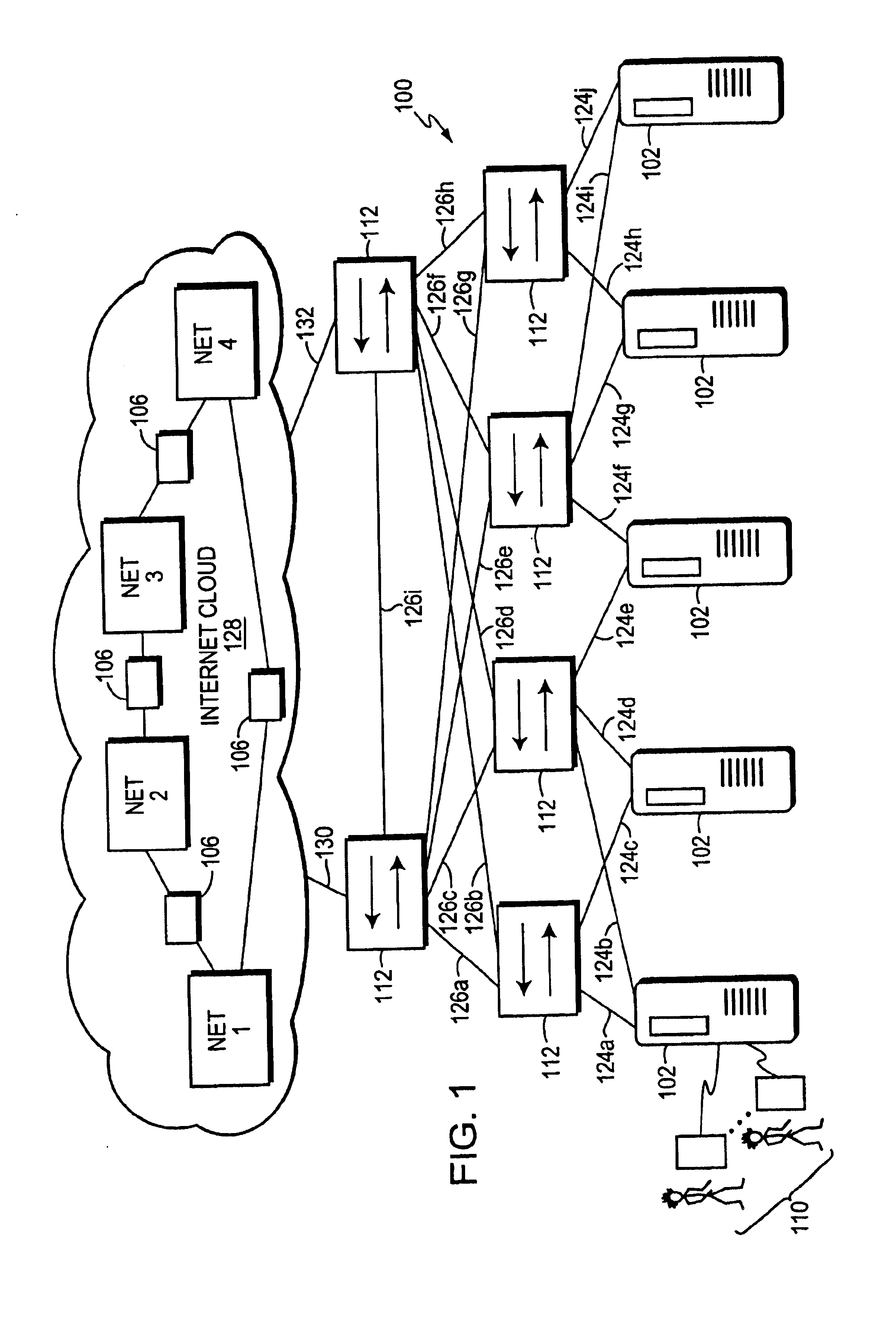
. 1 is a highly schematic illustration of a computer network 100. The network 100 includes a plurality of servers 102 that are preferably configured as web-hosting servers. A number of users 110 are shown connecting to one of the host 102, but typically there will a number of users that are connected to each host. The network 100 further includes a plurality of intermediate network devices 112, such as backbone routers, high-speed switches, etc. Each host 102 is preferably coupled to two or more of the devices 112 by respective trunks or links 124(a . . . j). Significantly, the network 100 is formed from a multitude of smaller networks, herein shown as NET 1-4. These smaller networks are interconnected together by routers 106. These smaller included networks, considered all together are the Internet 128. In a preferred embodiment, the devices 112 and the routers 106 may include similar designs. Links 126(a . . . i) interconnect devices 112, and links 130, 132 connect devices 112 to ...


PUM


Abstract

A method for policing traffic on a computer communications network having a multitude of nodes interconnected by various communications media. An individual policer is established at each node for monitoring and / or policing the traffic incoming to that node. Traffic policy parameters are established for traffic-classes and the policy is implemented at each individual policer. Thresholds may be established and when the thresholds are met or exceeded the individual policer will export the traffic conditions at the respective node. The other individual policers or a master policer will receive the exported information. -The individual policers police the traffic incoming to its associated node depending on the traffic condition information received from all the nodes. Several classes may be handled by each individual policer. Leaky bucket algorithms may be used in some instances.

Description

1. Field of the InventionThe present invention relates generally to computer communications networks, and more particularly to regulating, monitoring and policing traffic on such computer communications networks.2. Background InformationEnterprises, including businesses, governments and educational institutions, rely on computer networks to share and exchange information. A computer network typically comprises a plurality of entities interconnected by a communications media. An entity may consist of any device, such as a host or end station, that sources (i.e., transmits) and / or receives network messages over the communications media. A common type of computer network is a local area network ("LAN") which typically refers to a privately owned network within a single building or campus. A network device called a "bridge" is often used to implement "bridging" function between entities connected to a LAN. Typically, the bridge is a computer that includes a plurality of ports, which are...

Claims


Application Information

Patent Timeline
IPC IPC(8): H04L12/56
CPCH04L47/10H04L47/215H04L47/21H04L47/20
Inventor BHATTACHARYA, DIPANKARHUANG, YIRENKLOTH, RAYMONDPADWEKAR, KETAN A.
Owner CISCO TECH INC
Learn More