
Cabin situation alert system

a situation alert and cabin technology, applied in the field of warning and communication systems, can solve the problems of ill or disruptive passengers, smoke and/or fire, and endanger all passengers on board the aircra

Inactive Publication Date: 2004-11-16
BISSETT RICHARD L
View PDF8 Cites 11 Cited by
  • Summary
  • Abstract
  • Description
  • Claims
  • Application Information

AI Technical Summary

Benefits of technology

"The present invention provides a means for airline cabin crew to alert all other crewmembers of a developing hazardous situation. Each flight attendant carries a small portable receiver / transmitter device, which has a unique numerical designation and includes buttons for alerts. The portable receiver / transmitter sends a radio frequency signal to a central receiver / transmitter, which rebroadcasts the signal to all other portable receiver / transmitters. The portable receiver / transmitters vibrate and illuminate to alert the wearers to the situation. The invention also provides a storage location for the portable receiver / transmitters and prevents inadvertent removal of remote units from the aircraft. Other members of the cabin crew can come to the aid of the person sending the distress signal, based on the severity of the alert, and the cockpit crew can prepare for voice communications from the cabin crew and act accordingly to prescribed airline procedures."

Problems solved by technology

During a routine airline flight, situations can develop in the cabin that could potentially endanger all persons on board the aircraft.
These situations might involve equipment failure resulting in smoke and / or fire, an ill or disruptive passenger, or a hijacking.
A flight attendant must notify the cockpit crew and the other flight attendants of this situation, but he or she may not be able to use the normal cabin interphone system to do so.

Method used


Image

  • Cabin situation alert system
  • Cabin situation alert system
  • Cabin situation alert system

Examples


Embodiment Construction

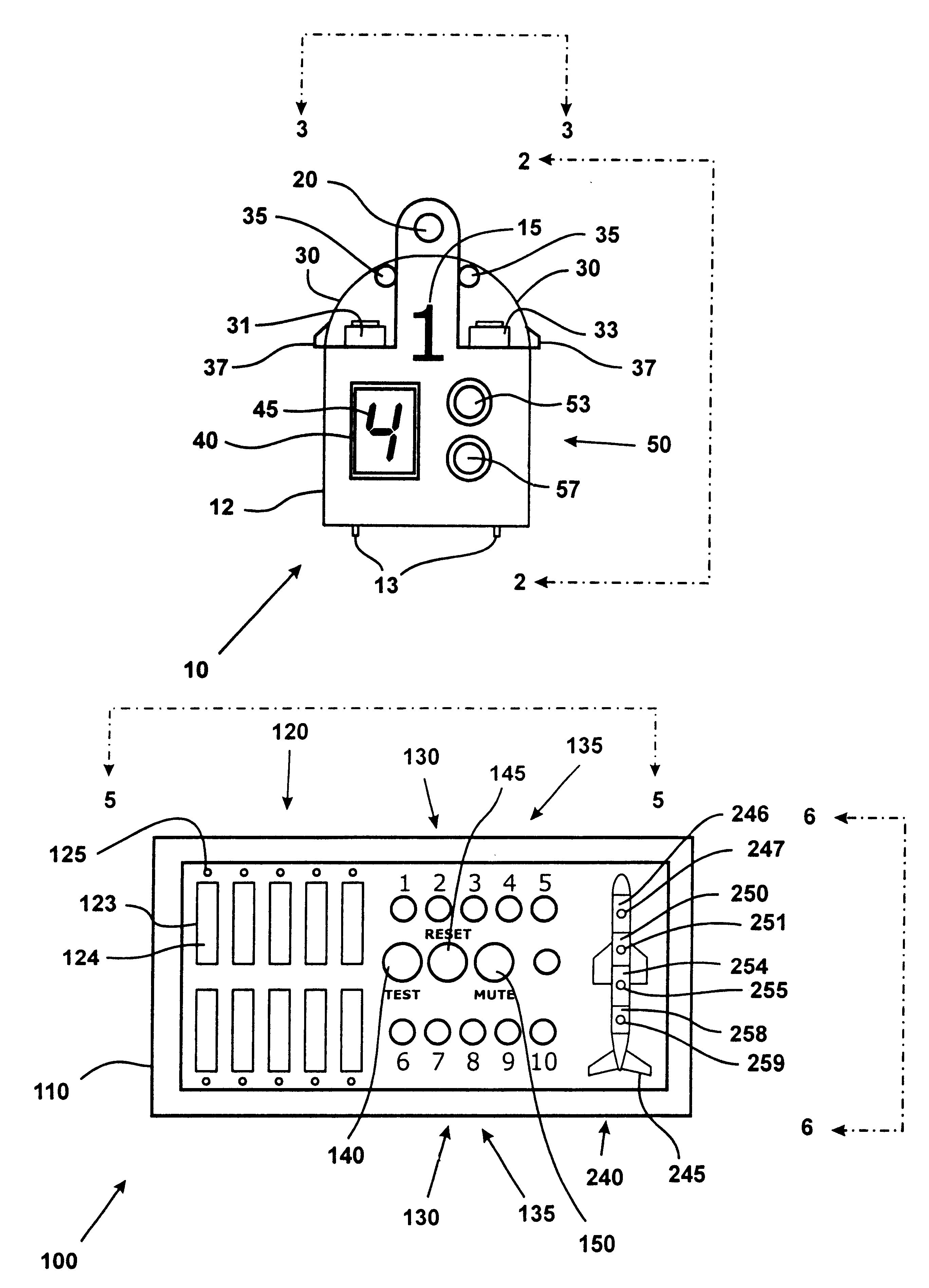
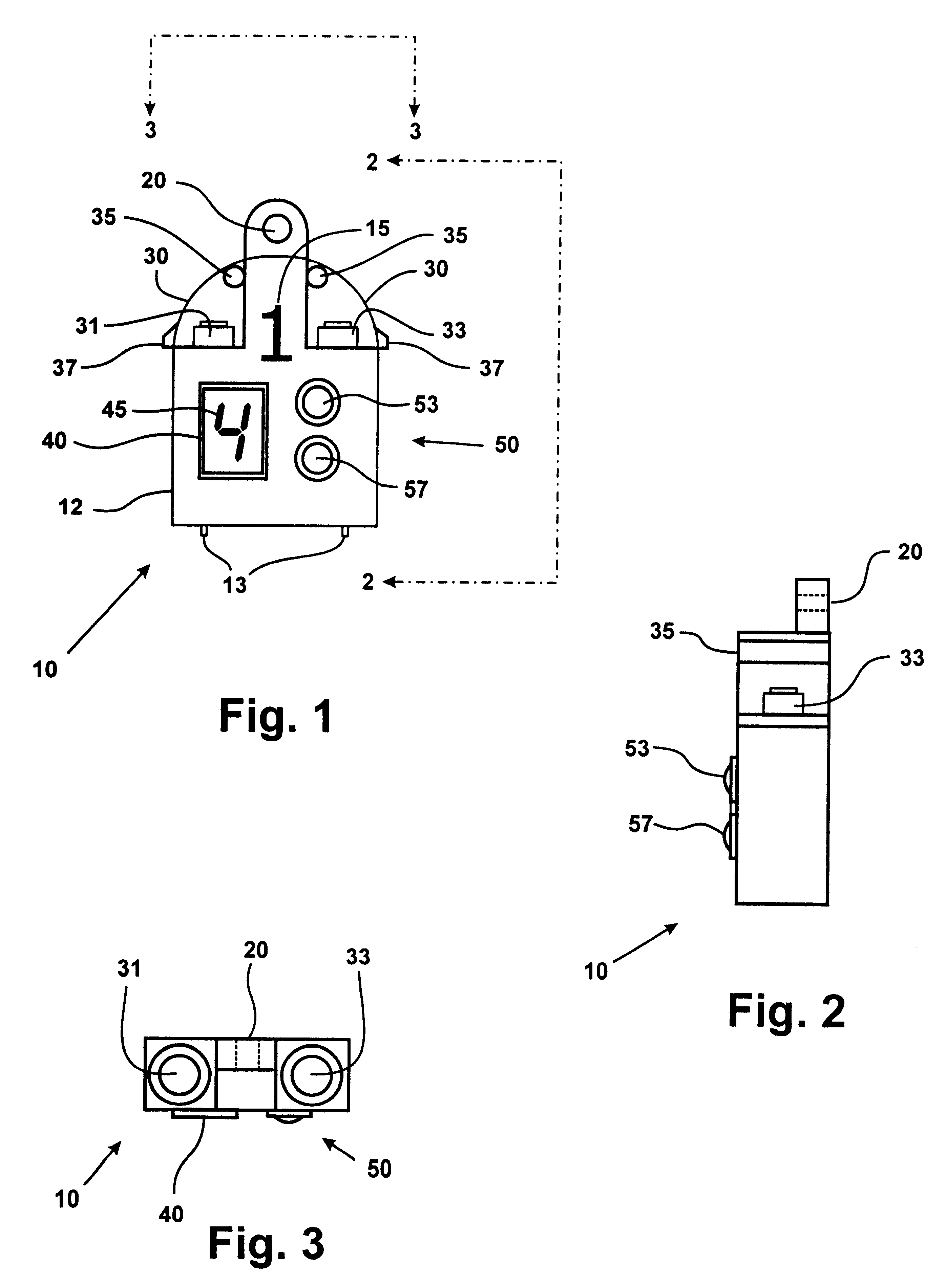
In accordance with the present invention, FIGS. 1, 2, and 3 show the portable receiver / transmitter 10. All components are contained within or mounted to case 12, which is made of high-impact plastic or other suitable material. Portable receiver / transmitter 10 is secured around a flight attendant's neck or to his or her belt by means of lanyard attach point 20. Portable receiver / transmitter 10 is identified by its numerical designator 15. Red alert button 33 and yellow alert button 31 are protected from inavertent actuation by protective covers 30, which may be made of clear or opaque high impact plastic or other suitable material. Thumb tabs 37 provide means to easily open protective covers 30, which pivot on hinges 35. Lights 50 comprise a red light 53 and a yellow light 57. These lights illuminate in response to the actuation of the red or yellow alert button on another portable receiver / transmitter. Display 40 has a numerical indication 45 of which other portable receiver / transmi...


PUM


Abstract

Each flight attendant would carry a small portable receiver / transmitter device, similar in size to a pager, and a central receiver / transmitter located in the cockpit. Each portable receiver / transmitter has a numerical designation (1, 2, 3, etc.) which is unique to that one device. The portable receiver / transmitter has two buttons (yellow alert and red alert), a numerical display, indicator lights, and a vibrator. In a developing situation, a nearby flight attendant presses either the yellow or red alert button (depending on the severity of the situation), producing a radio frequency (RF) signal. The central receiver / transmitter receives, processes, and re-broadcasts the signal to all other portable receiver / transmitters worn by flight attendants. The portable receiver / transmitters vibrate to alert the wearers to the situation. A light (either red or yellow) illuminates on all portable receiver / transmitters, and the numerical designation of the sending receiver / transmitter appears on the displays. In addition, a light corresponding to the sending receiver / transmitter's numerical designation appears on the central receiver / transmitter, as well as an audible alarm sound.

Description

I FIELD OF THE INVENTIONThis invention relates to warning and communications systems, particularly for use in airborne commercial aircraft to alert the flight (cockpit) crew and flight attendants of a potentially dangerous situation in the passenger compartment (cabin).II BACKGROUND OF THE INVENTIONDuring a routine airline flight, situations can develop in the cabin that could potentially endanger all persons on board the aircraft. These situations might involve equipment failure resulting in smoke and / or fire, an ill or disruptive passenger, or a hijacking. A flight attendant must notify the cockpit crew and the other flight attendants of this situation, but he or she may not be able to use the normal cabin interphone system to do so.The Cabin Situation Alert System (CSAS) is designed to immediately inform the cockpit crew and cabin crew of a developing situation in the cabin without using the normal interphone system. In most cabin emergencies times of notification and response we...

Claims


Application Information

Patent Timeline
Patent Type & Authority Patents(United States)
IPC IPC(8): B64D45/00G08B25/01G08B27/00
CPCB64D45/0015G08B27/008G08B25/016B64D2045/0045B64D45/0059
Inventor BISSETT, RICHARD L.
Owner BISSETT RICHARD L
Learn More