Electrohydraulic setting device

a technology of electrohydraulic setting and hydraulic system, which is applied in the direction of rod connection, piston pump, fluid coupling, etc., can solve the problems of increasing the risk of fire, complicated hydraulic system fitting onboard aircraft, and high cost of hydraulic system

Inactive Publication Date: 2004-11-09
SAAB AB
View PDF8 Cites 6 Cited by
  • Summary
  • Abstract
  • Description
  • Claims
  • Application Information

AI Technical Summary

Benefits of technology

The hydraulic pump consists of a pump cylinder in which a piston slides at a specified frequency in a reciprocating motion within the pump cylinder. The piston's motion is controlled through its functioning as the rotor for the linear electronic motor, with the motor's stator coil being wound around the pump cylinder itself. Moreover, the piston functions as a pump piston for pumping hydraulic fluid to the slave cylinder. An additional feature is that the piston also functions as a valve for opening and closing compression and suction ducts for carrying hydraulic fluid to and from the slave cylinder during the piston's reciprocating motion. By pumping hydraulic fluid at a high frequency, high pressure can be built up and great force exerted on the slave piston in the cylinder, even when the hydraulic pump is small.
Because of the high working frequency and the large ratio between the cross-sectional area of the piston in the slave cylinder and the cross-sectional area of the piston in the pump, a high exchange of power can be achieved between the pump and the slave piston. This enables great actuating forces to be achieved from a very spatially economic and weight-effective manoeuvring device in the form of the actuating device being described here. As a result of this, it would be possible to achieve a distributed system of local hydraulic actuators, in a set-up such as a craft, for manoeuvring mechanical elements in a craft, where the actuators are driven and controlled electrically. Consequently, the need for a network of hydraulic lines and central hydraulic systems characteristic of current technology previously mentioned could be done away with.
In those applications where a mechanical element, for example an aileron, manoeuvred by an actuator is affected by other external forces so that the element is forced back to a neutral position, these external forces can be utilised for regeneratively re-supplying the power back to the actuator's electrical supply. This would reduce the cooling requirements of the hydraulic fluid in the actuator, thus contributing to the energy efficiency of the set-up.
The linear motor's principal coil, that is the stator coil, may consist of a simple coil, though it is advantageous to use multi-phase winding. This can make it easier to steer the forces during the piston stroke in each respective direction, and therefore facilitate optimisation of the actuator's efficiency.
In those cases where it is desired that the slave piston rod in the actuator moves in the opposite direction to that described above, this can be easily achieved by having the pump piston position around the central axle work in reverse phase, i.e. that if the pump piston with its movement in one direction has a rotational position v while working to drive the rod outward from the slave cylinder, then the piston's action with movement in the same direction but with the piston rotation position advanced to .nu.+ the rotation interval (depending on how the inlet and outlet ducts are distributed around the pump cylinder), will bring about pump work where the slave piston rod is forced inwards into the slave cylinder instead of outwards.

Problems solved by technology

All in all, this means that rather complicated hydraulic systems must be fitted onboard aircraft.
Having hydraulic lines running throughout an aircraft increases the risk of fire, as hydraulic fluid may leak into sensitive areas.
Moreover, hydraulic systems are expensive and increase the probability of failure.
Serviceability is also reduced since the hydraulic system is distributed throughout the craft, where certain parts can be difficult to replace.
Perhaps the greatest weakness of hydraulic systems in this context is the difficulty encountered actually installing hydraulic manoeuvring systems of the type mentioned here within aircraft or for that matter any sort of technical machine.
This has not been possible yet, as actuators suitable for these purposes are not yet available.

Method used


Image

  • Electrohydraulic setting device
  • Electrohydraulic setting device
  • Electrohydraulic setting device

Examples


Embodiment Construction

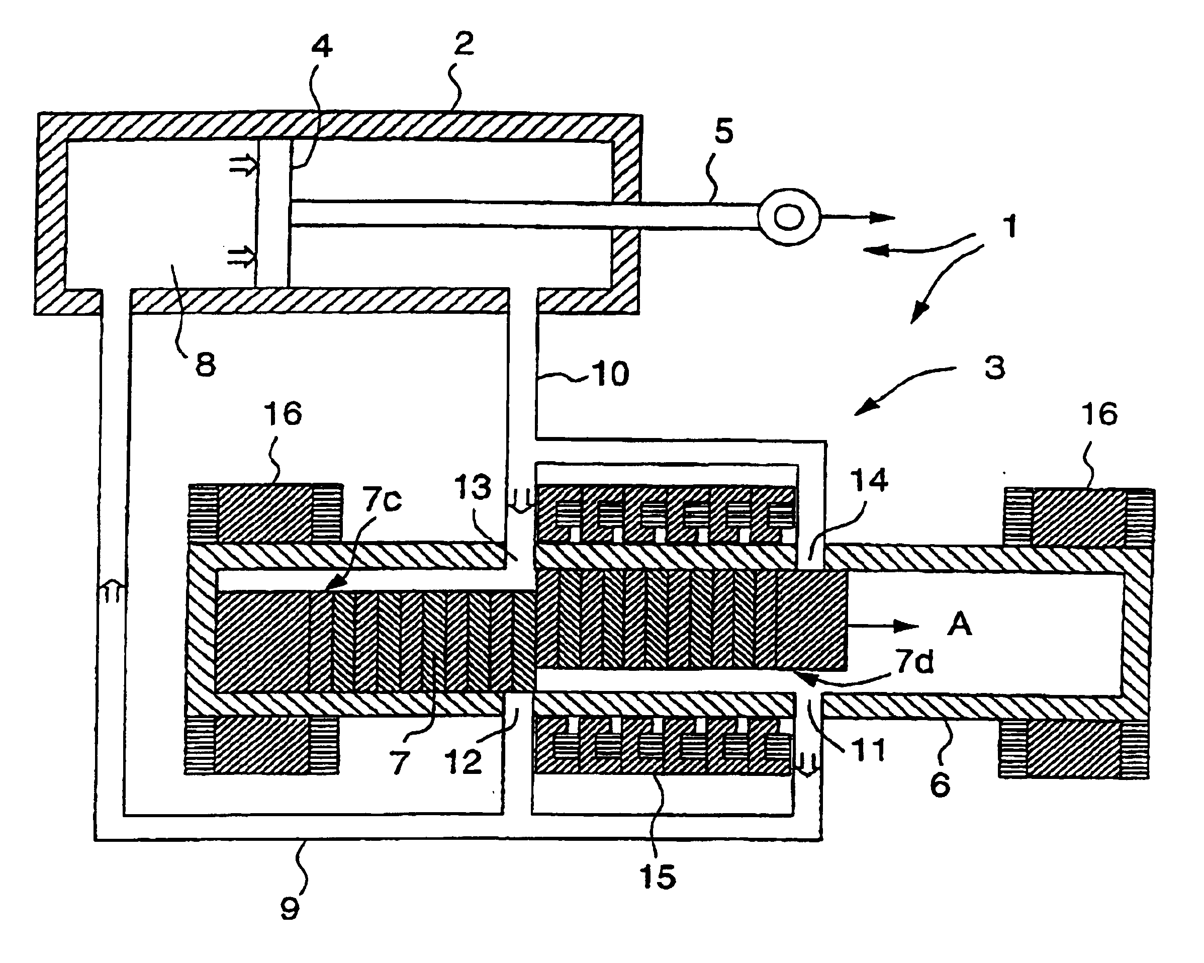
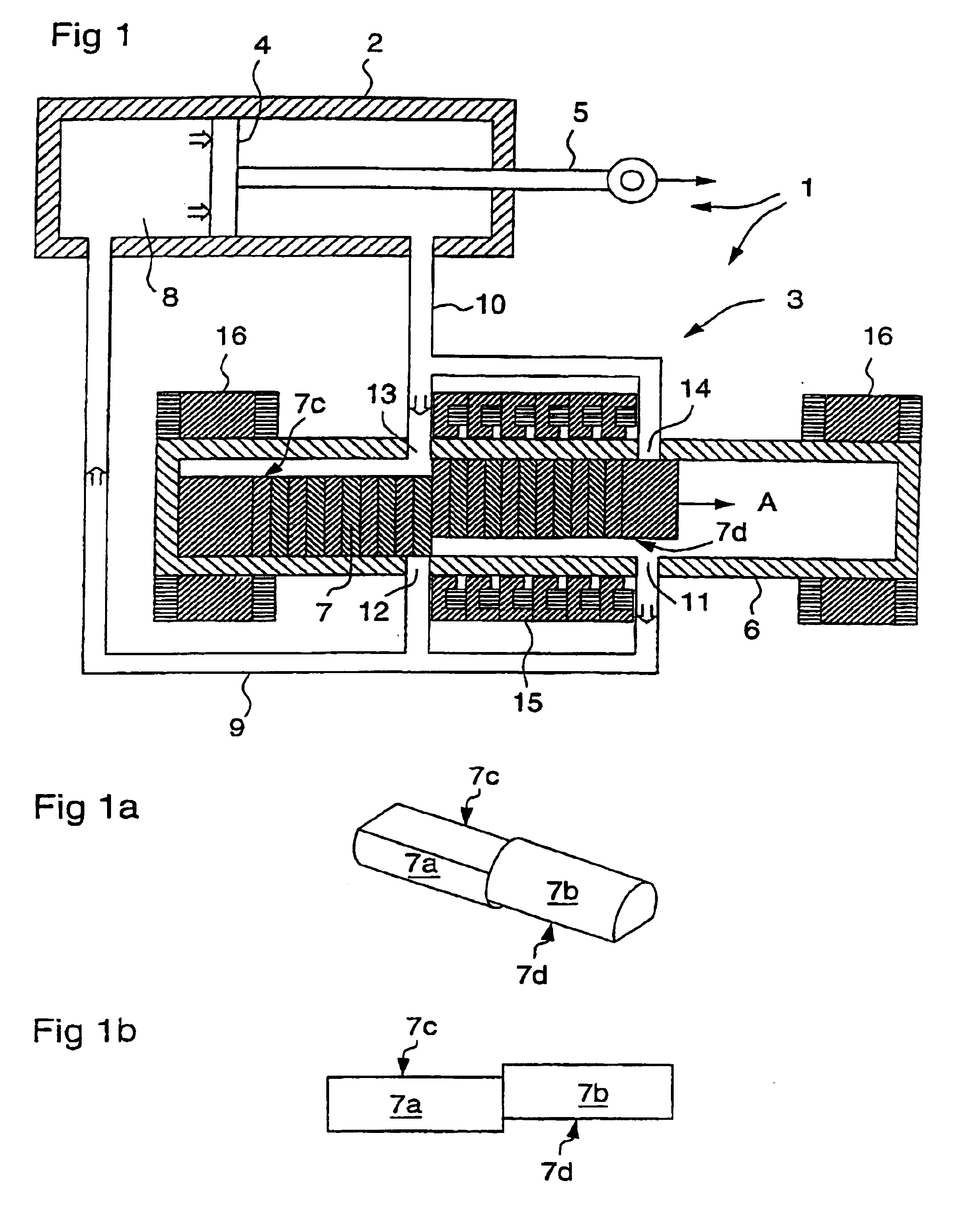
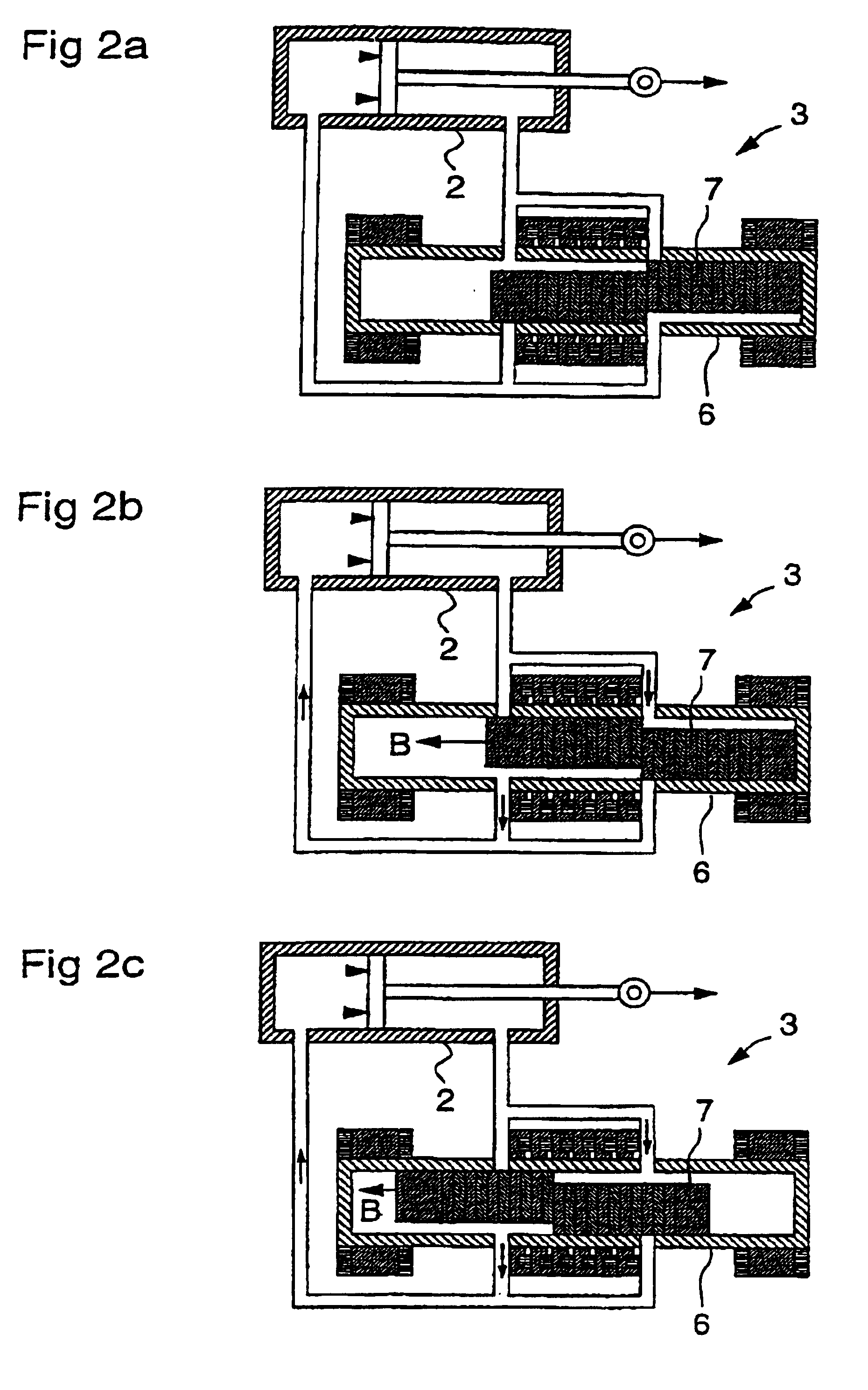
In accordance with the invention, an electrohydraulic actuating device is presented, consisting of a hydraulic slave cylinder containing a piston that pushes a piston rod and which receives its pressure for building up this piston-derived power via its integration with a hydraulic pump, which is in turn is driven by a linear electric motor.

The hydraulic pump consists of a pump cylinder in which a piston slides at a specified frequency in a reciprocating motion within the pump cylinder. The piston's motion is controlled through its functioning as the rotor for the linear electronic motor, with the motor's stator coil being wound around the pump cylinder itself. Moreover, the piston functions as a pump piston for pumping hydraulic fluid to the slave cylinder. An additional feature is that the piston also functions as a valve for opening and closing compression and suction ducts for carrying hydraulic fluid to and from the slave cylinder during the piston's reciprocating motion. By pum...


PUM


Abstract

An actuating device (1) for carrying out mechanical work by means of a slave piston rod (5) in a hydraulically-operated slave cylinder (2), where the actuating device (1) is made up of a hydraulic pump (3) integrated with a slave cylinder (2) and where the hydraulic pump (3) is driven by a linear electric motor, which consists of a pump piston (7) which is used as rotor in the linear motor at the same time as the pump piston (7) functions as a pumping piston in the hydraulic pump (3) to build up a hydraulic pressure in the slave cylinder (2).

Description

The invention in question concerns an actuating device, consisting of a hydraulic slave-cylinder integrated with a hydraulic pump, which with the assistance of a linear electric motor drives the pump piston in a reciprocating motion within a pump cylinder thereby building up hydraulic pressure to the level desired for driving a piston in the slave cylinder, thus enabling a piston rod connected to the piston in the slave cylinder to execute mechanical work.STATE OF THE ARTLinear hydraulic actuators are used today in, for example, the aircraft industry, where they are used for manoeuvring flight control surfaces such as ailerons. The type of actuator referred to here is also used in railway construction, for example for tilting railway wagon bodies through curves. There are of course numerous other applications found in a range of technological areas. Applications within the aircraft industry have been used in this document to describe the current technology along with its possible li...

Claims


Application Information

Patent Timeline
Patent Type & Authority Patents(United States)
IPC IPC(8): B64C13/00B64C13/50B64C13/40F15B7/00F15B7/08
CPCB64C13/40F15B7/08B64C13/50Y10T137/86646F04B17/03F04B17/04F04B7/06H02K33/16
Inventor MALMQUIST, ANDERSKJELLQUIST, PETER
Owner SAAB AB
Why Eureka
Try Eureka