
Noncontacting finger seal

a finger seal and non-contact technology, applied in the direction of engine seals, leakage prevention, machines/engines, etc., can solve the problems of reducing the life of the seal, unsuitable for this purpose, and substantial adverse effects on the performance of the functions

Inactive Publication Date: 2004-11-02
NAT AERONAUTICS & SPACE ADMINISTATION UNITED STATES OF AMERICA THE AS REPRESENTED BY THE SEC
View PDF26 Cites 91 Cited by
  • Summary
  • Abstract
  • Description
  • Claims
  • Application Information

AI Technical Summary

Benefits of technology

"The present invention provides a finger seal apparatus that can be used in high speed and temperature environments such as gas turbine engines. The finger seal can be interposed between relatively high and low pressure cavities to provide sealing along a rotating member. The finger seal can be interposed between an upstream region of relatively high fluid pressure and a downstream region of relatively lower fluid pressure to prevent fluid leakage therebetween. The finger seal can provide noncontact sealing along a rotating member and can be used in annular sealing apparatus. The finger seal can include lift pads that can lift away from the rotating member and run on a thin film of fluid upon sufficient rotational speed of the rotating member or hydrostatic pressure loading adjacent the lift pad. The finger seal can be used in various applications such as gas turbine engines, aerospace, and hydraulic systems."

Problems solved by technology

Loss of compressed air from the secondary flowpath through leakage can have a substantial adverse effect on the performance of these functions.
Even small amounts of oil in the bleed air can render it unsuitable for this purpose.
Further, oil leakage can lead to coking of the seal, and ultimately reduced seal life.
A problem with finger seals is that at high shaft speeds, the rubbing contact between the fingers and the rotating surface can cause excessive heating of the components, which in turn lowers the durability and ultimately limits the life of the seal.
The problem is further aggravated when the seal is used in high temperature applications.
Accordingly, the desired sealing is undermined leading to engine inefficiencies.

Method used


Image

  • Noncontacting finger seal
  • Noncontacting finger seal
  • Noncontacting finger seal

Examples


Embodiment Construction

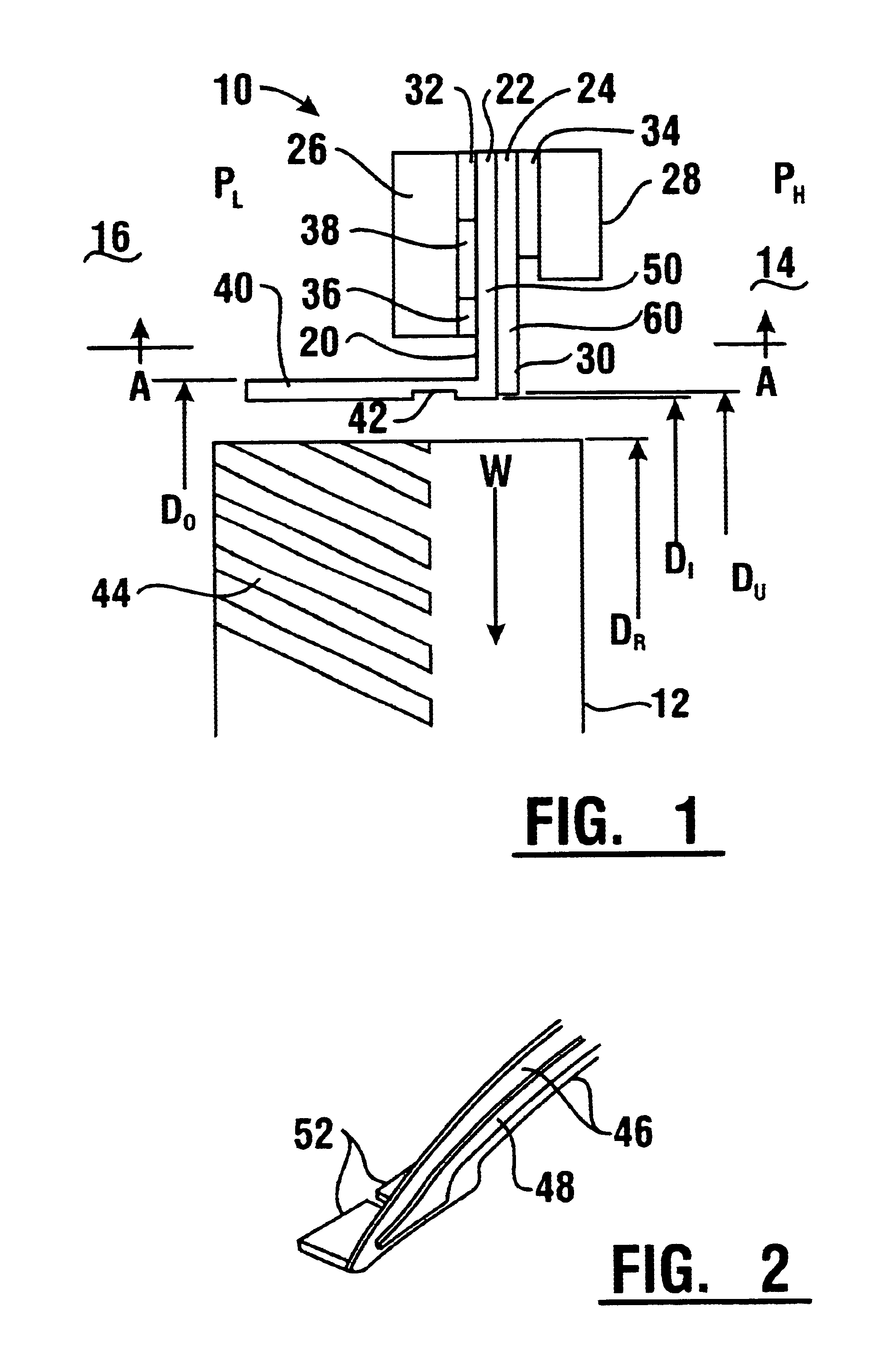
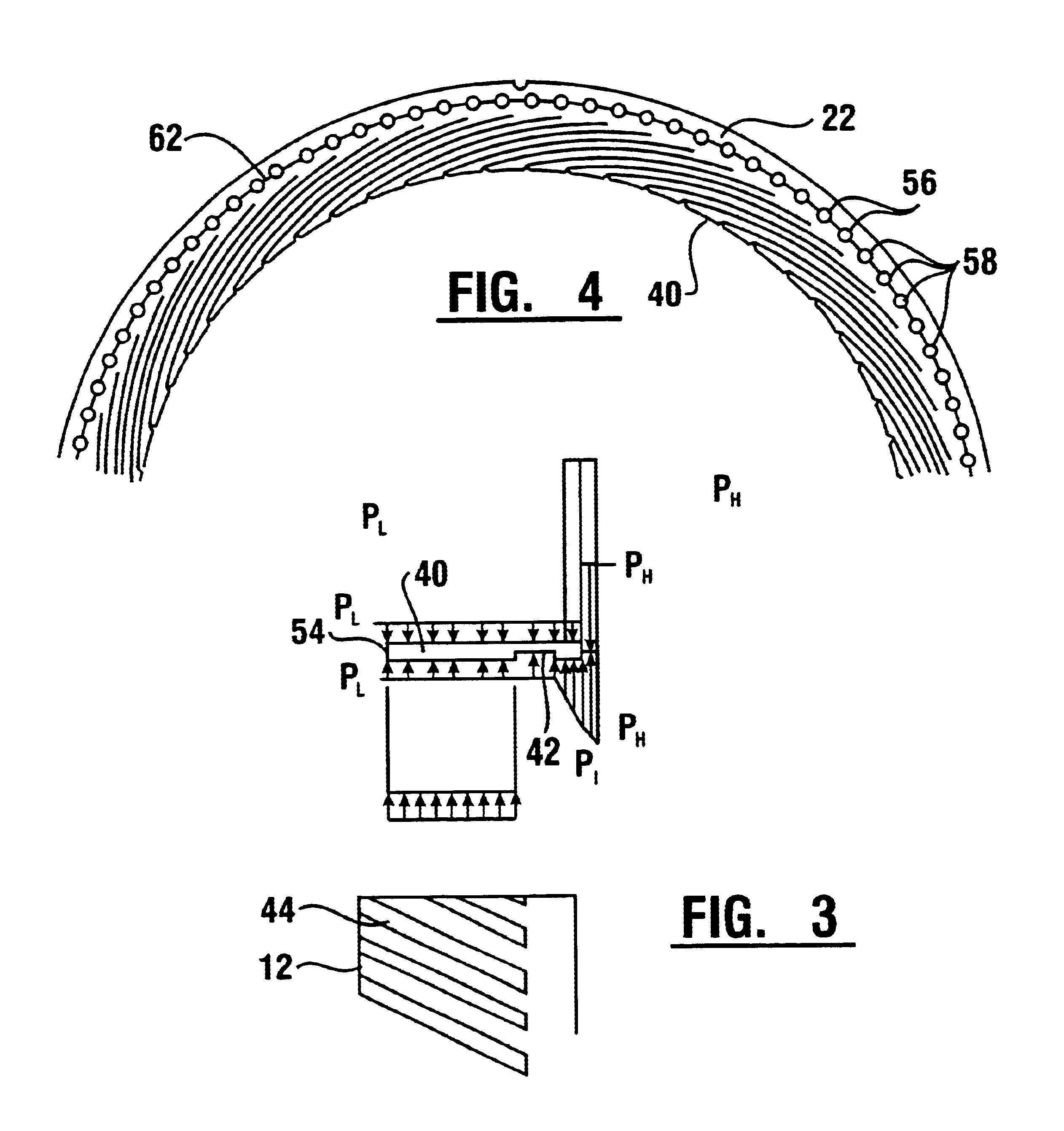
Referring now to the drawings and particularly to FIG. 1, there is shown therein a sectional view of an embodiment of a finger seal apparatus of the present invention. FIG. 1 shows a noncontacting finger seal apparatus (which hereinafter may alternatively be referred to as "seal" or "finger seal" or "seal apparatus") 10 adjacent a rotatable member 12 and intermediate an upstream zone or region 14 of relatively high fluid pressure (P.sub.H) and a downstream zone or region 16 of relatively lower fluid pressure (P.sub.I). The finger seal apparatus 10 can include axially juxtaposed annular comb-like members or finger elements 22, 24. Each finger element can have a plurality of uniformly spaced and integral comb-like teeth or fingers. A finger element may comprise a whole ring with a plurality of fingers. Further example and discussion of various components of a finger seal may be found in U.S. Pat. Nos. 5,755,445 and 6,196,550, the disclosures of which are incorporated herein by referen...


PUM


Abstract

An annular finger seal is adapted to be interposed between a high pressure upstream region and a lower pressure downstream region to provide noncontact sealing along a rotatable member. The finger seal comprises axially juxtaposed downstream and upstream finger elements, each having integrally spaced fingers. The downstream fingers each have a lift pad, whereas the upstream fingers lack a pad. Each pad extends in a downstream direction. Each upstream finger is spaced from the rotating member a greater distance than each pad. Upon sufficient rotational speed of the rotating member, each pad is operative to lift and ride on a thin film of fluid intermediate the rotating member and the pad.

Description

ORIGIN OF THE INVENTIONThe invention described herein was made by employees of the United States Government and may be manufactured and used by or for the Government of the United States of America for governmental purposes without the payment of any royalties thereon or therefor.This invention relates in general to a sealing apparatus. More particularly, this invention relates to a finger seal apparatus which is adapted to be interposed between relatively high and low pressure cavities to provide sealing along a rotating member.Gas turbine engines can employ sealing devices in various capacities where it is necessary to restrict the flow of fluid or gases from one portion of the engine to another. A common use is for separating the primary engine flowpath from the secondary flowpath. The primary engine flowpath directs the flow of gases to the compressor and turbine stages, from which the engine derives thrust or power. The secondary flowpath comprises a series of conduits for deli...

Claims


Application Information

Patent Timeline
Patent Type & Authority Patents(United States)
IPC IPC(8): F16J15/16F16J15/44F16J15/32
CPCF16J15/164F16J15/441F16J15/3288
Inventor PROCTOR, MARGARET P.STEINETZ, BRUCE M.
Owner NAT AERONAUTICS & SPACE ADMINISTATION UNITED STATES OF AMERICA THE AS REPRESENTED BY THE SEC
Learn More