
Apparatus and method for providing a cyclic buffer using logical blocks

a logical block and buffer technology, applied in the field of buffers, can solve the problems of information being overwritten, inability to allocate an area, and inefficient use of buffer space,

Inactive Publication Date: 2004-10-19
ORACLE INT CORP
View PDF9 Cites 49 Cited by
  • Summary
  • Abstract
  • Description
  • Claims
  • Application Information

AI Technical Summary

Benefits of technology

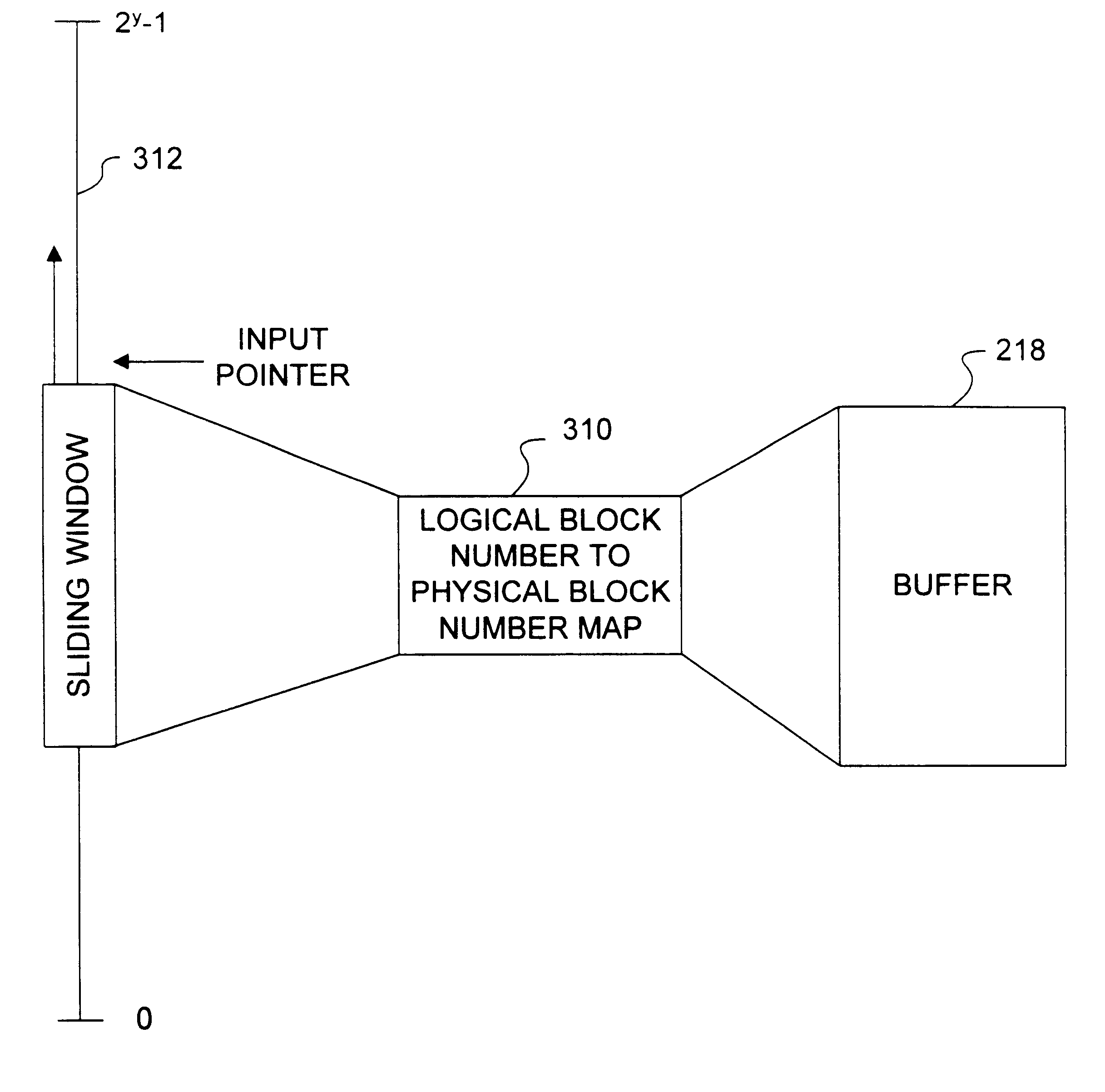
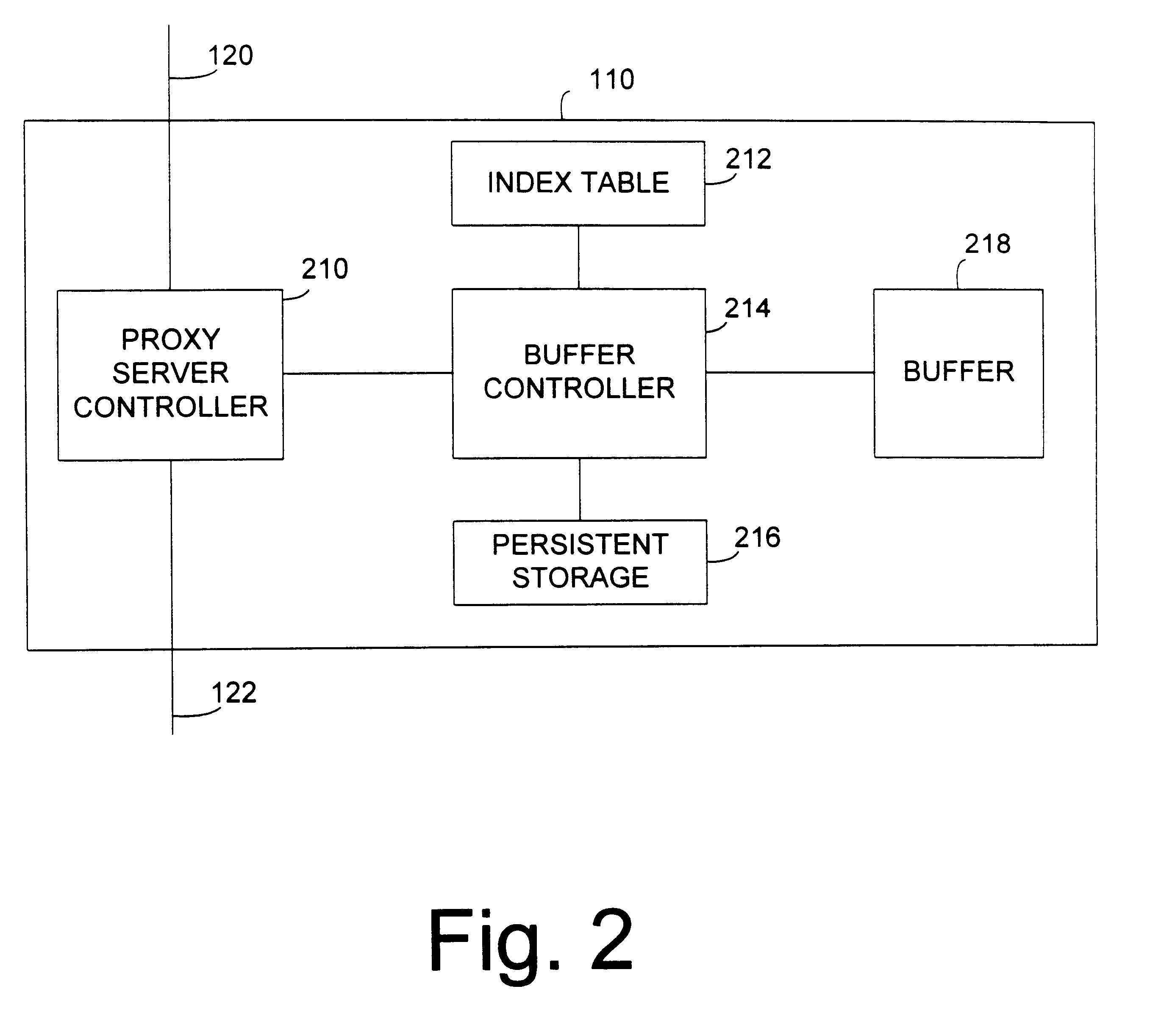
The buffer manager accesses the buffer contents by consulting the index to determine the logical blocks associated with desired information, and maps logical block numbers to physical buffer blocks. The logical block numbers allow the buffer manager to simply determine the newness of a logical buffer block, as well as whether the block is obsolete.
Such systems and methods overcome the problems of conventional cyclic buffers described above. Additional advantages of the invention are apparent from the description which follows, and may be learned by practice of the invention. It is to be understood that both the foregoing general description and the following detailed description are exemplary and explanatory only and are not restrictive of the invention, as claimed.

Problems solved by technology

It is not possible to allocate an area in a cyclic buffer that wraps around the buffer.
This is an inefficient use of buffer space.
If the size of a cyclic buffer is large, information being overwritten may already be expired.
Unfortunately, locating the indexes of information stored in a cyclic buffer that has been overwritten is quite complicated and is also quite time-consuming.
The requirement of both a cycle number and block number, and the algorithms that must be implemented to use them, make a conventional cyclic buffer very cumbersome.

Method used


Image

  • Apparatus and method for providing a cyclic buffer using logical blocks
  • Apparatus and method for providing a cyclic buffer using logical blocks
  • Apparatus and method for providing a cyclic buffer using logical blocks

Examples


Embodiment Construction

Systems and methods consistent with the improved cyclic buffer disclosed herein use an index to map consecutively numbered logical blocks to physical buffer blocks of a cyclic buffer. The index to the cyclic buffer is implemented using the logical block numbers. When new information is added to the cyclic buffer, the next logical block number is assigned to the information. The new logical block number corresponds to a physical cyclic buffer block. The new logical block number and key associated with the information are then added to the index. The mapping of logical block numbers to physical block numbers may simply be a mathematical formula that defines the relationship between the logical block numbers and physical block numbers.

To retrieve information from the cyclic buffer, the index is first scanned to determine whether an index entry exists that has a key associated with the information. If such a key is present, the entry is accessed to determine the logical block number ass...


PUM


Abstract

An apparatus and method for creating and maintaining a cyclic or circular buffer are implemented using logical blocks corresponding to the physical blocks of the buffer. The logical blocks are mapped to the physical blocks of the cyclic buffer, and are used to create an index table for the buffer. Each entry in the index table corresponds to one or more blocks in the buffer, and has a logical block number respectively associated with a buffer block. When information from the buffer is accessed, the index table is consulted to determine if the requested information is stored in the buffer. If the information is stored in the buffer, the logical block number corresponding to the information is retrieved from the entry and translated into a corresponding physical block number. Using logical block numbers allows simple determination of whether the buffer block is valid, and how new or fresh the buffer block is without requiring a generation or cycle number.

Description

I. BACKGROUND OF THE INVENTIONA. Field of the InventionThe present invention relates generally to buffers, and in particular to an apparatus and method for creating and maintaining a cyclic or circular buffer.B. Description of the Prior ArtA buffer is a memory area used for storing information being transferred between two entities. It is often used to decouple concurrently executing software processes so that a process reading from the buffer and a process writing to the buffer may operate at different speeds or on different block sizes of information stored in the buffer. An input pointer is used to identify a location in the buffer to write information.A cyclic or circular buffer is a special type of buffer that uses a cyclic addressing scheme. Data is input to the buffer at the buffer location pointed to by the input pointer. The input pointer is incremented each time data is input to the buffer. When the input pointer reaches the end of the buffer, it is wrapped around to the b...

Claims


Application Information

Patent Timeline
Patent Type & Authority Patents(United States)
IPC IPC(8): G06F5/06G06F5/10G06F12/02G06F12/00
CPCG06F5/10
Inventor WONG, THOMAS K.TSIRIGOTIS, PANAGIOTISCHAWLA, RAJEEVAHMADIAN, OMIDRADIA, SANJAY R.
Owner ORACLE INT CORP
Learn More