
Capacitive sensors in vehicular environments

a technology of capacitive sensors and vehicular environments, applied in the direction of vehicular safety arrangements, pedestrian/occupant safety arrangements, transportation and packaging, etc., can solve the problems of passenger serious injury, deficiency of current sensors in many regards, and considerable variation in passenger acceleration

Inactive Publication Date: 2004-09-21
METHODE ELETRONICS INC
View PDF18 Cites 104 Cited by
  • Summary
  • Abstract
  • Description
  • Claims
  • Application Information

AI Technical Summary

Benefits of technology

FIG. 14 shows the long-term drift of capacitive signals due to temperature effects for a vehicular sensor;

Problems solved by technology

Because of differing vehicle geometries and extreme environmental conditions to which they are subjected, the sensors presently available are deficient in many regards.
For example, if the passenger is seated too far forward, or has his / her head too far forward, occupying the space into which the air bag will deploy, the passenger may be seriously injured by the deployment of the air bag intended to prevent passenger injury.
But even if the passenger is not too far forward at the beginning of the collision, the passenger will tend to move rapidly forward, with the passenger's head leading that motion, relative to the vehicle, as the vehicle rapidly decelerates, and will tend to move into the air bag deployment space, at least in the case of forward collisions, and may be too far into the air bag deployment space, before the completion of air bag deployment, to escape injury from the air bag deployment.
Also variation of the crash intensity by itself will cause considerable variation in passenger acceleration.

Method used


Image

  • Capacitive sensors in vehicular environments
  • Capacitive sensors in vehicular environments
  • Capacitive sensors in vehicular environments

Examples


first embodiment

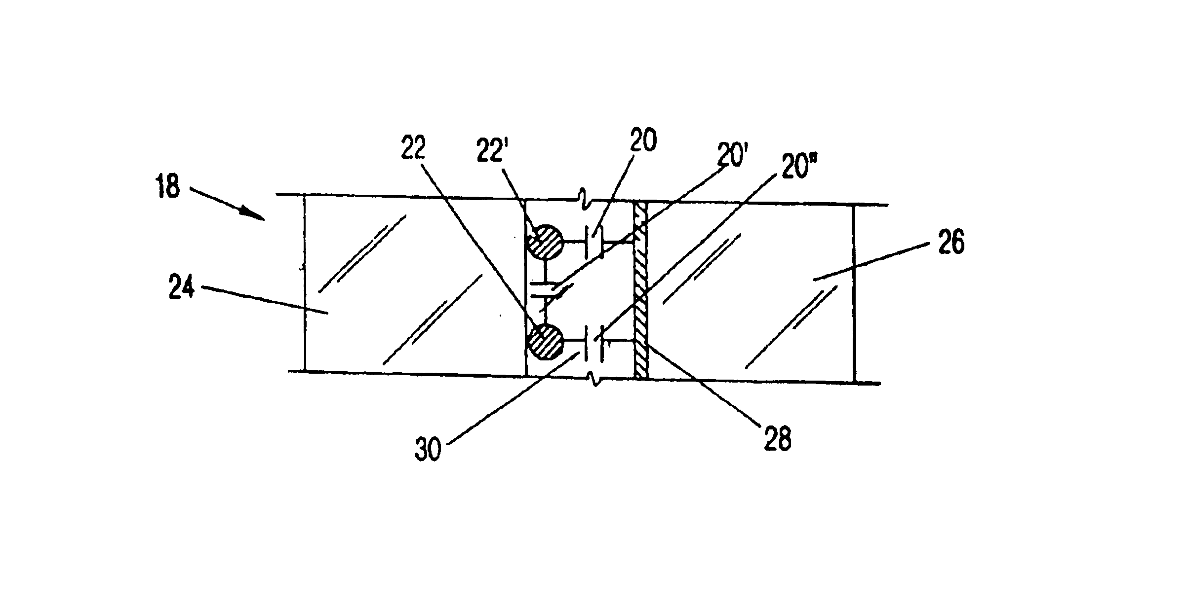
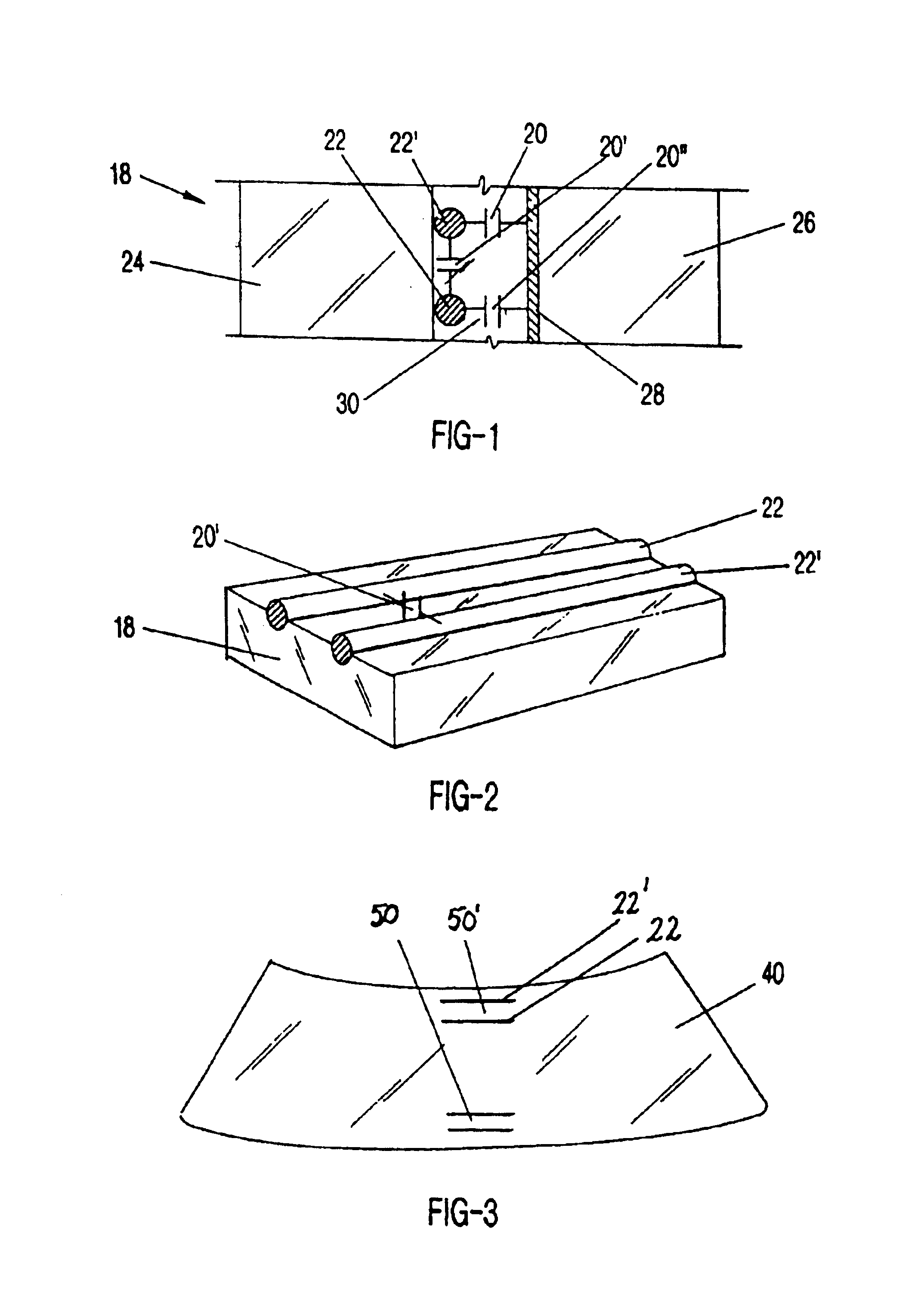
the present invention is applicable to equivalent constructions, methodologies, and applications, including the following: 1) detecting glass deflection as an indication of possible intrusion, such as a burglary attempt; 2) detecting glass deflection as an indication of potential breakage, such as the effect of a strong windstorm on plate glass used in buildings; 3) forming the electrodes on a surface of a transparency product; 4) integrating the electrodes in or on multiple discrete transparency products, such as front and rear vehicle windows; and 5) employing equivalent devices spatially distributed on the windshield or other transparency product, to provide multiple points of detection of a crash pulse, such as accelerometers or strain gauges.

Conductive membrane or coating 28 depicted in FIGS. 1 and 11 (discussed below) and discussed herein can be suitable visually-transparent electroconductive coatings that can be used or are present with the windshield substrate including thos...

second embodiment

In the present invention, a capacitive sensor or sensors are used in a system for detecting a visibility condition of a transparency product. The system distinguishes between a visibility condition and an object in proximity to the transparency product and the system can operate in conjunction with a vehicle occupant protection system to distinguish between a vehicle occupant in proximity to the transparency product and a visibility condition. The system further initiates a response to modify the visibility condition.

Transparency products, such as windshields, are also subject to diminished visibility conditions from the presence of condensing moisture on the interior or exterior surface. The condensing moisture can be either in liquid form, such as condensed fog or rain drops, or in solid form, such as frost, snow or ice. In a second embodiment, the present invention is also a system for detecting a visibility condition of a transparency product and initiating a response to modify ...

third embodiment

the present invention is understood to include equivalent forms, methodologies, and applications. For example, the rigid or semi-rigid panel may be formed of non-conductive material to which is applied a conductive film thus forming the ground plane to which the capacitive sensor electrodes are applied; the conductive film may comprise the driven shield element, as described in the Vranish patent; the cutting edges of the panel may be any number of one or greater, e.g. an oval shape, rectangular shape, or polygonal shape; the reference sensor may be fabricated on a printed circuit board, on the sensor substrate, or in other manners that accomplish the intent of detecting changes in conductivity and / or thickness of the covering material; the positioning of the ASIC may be in any convenient location on or near the panel; the multiple sensors may comprise any number of sensors greater than one; the triangulation sets may use various assignments of the multiple sensors; the discriminati...


PUM


Abstract

Capacitive sensors used to detect force upon a transparency product for detecting and discriminating crash characteristics of a vehicle, as well as capacitive sensors used in conjunction with a conductive panel functioning as an airbag cover and ground plane for the capacitive sensors. The capacitive sensors are made up of electrodes, of which one may be a conductive coating. The capacitive sensors can be arranged upon a substrate and can include a reference sensor. Long term effects of temperature upon sensor output are compensated for with an algorithm comparing constant desired sensor output to low frequency drift due to temperature effects. Moisture upon a transparency product is distinguished from a nearby object due to the capacitance sensed. A sleep detection algorithm detects when a vehicle operator is drowsy. A capacitive sensor array having a nested circle sensor and L-shaped sensors, along with a dummy sensor is used in a sunroof-equipped vehicle for sensing occupant head position.

Description

1. Field of the Invention (Technical Field)The present invention relates to capacitive sensors, particularly those employed in automotive vehicular environments.2. Background ArtSensor technologies are becoming increasingly important in the development of safety and convenience features of vehicles. Because of differing vehicle geometries and extreme environmental conditions to which they are subjected, the sensors presently available are deficient in many regards.Automobile air bag systems are a well known means of attempting to reduce the likelihood of serious injury to passengers in collisions. These systems are designed to very quickly inflate an air bag in front of a passenger during a collision, so as to hopefully prevent the passenger from colliding with hard objects in the passenger compartment interior, particularly the steering column and / or the dashboard. Such systems typically sense that the vehicle is involved in a collision, by using an accelerometer to sense sudden de...

Claims


Application Information

Patent Timeline
Patent Type & Authority Patents(United States)
IPC IPC(8): B60N2/00B60H1/00B60R21/01B60R21/013B60R21/0136B60R21/015
CPCB60H1/00742B60N2/002B60R21/013B60R21/01532B60R21/0152B60R21/0136B60R2021/01302B60N2/0035B60N2210/12
Inventor KITHIL, PHILIP W.
Owner METHODE ELETRONICS INC
Learn More