
Magnetic head device having suspension with microactuator bonded thereto

a technology of magnetic head and microactuator, which is applied in the direction of maintaining the head carrier alignment, recording information storage, instruments, etc., can solve the problems of deteriorating manufacturing efficiency, heterogeneous mixed state of curing agent and epoxy solution, and deteriorating the reliability of a magnetic head devi

Inactive Publication Date: 2004-09-14
TDK CORPARATION
View PDF6 Cites 56 Cited by
  • Summary
  • Abstract
  • Description
  • Claims
  • Application Information

AI Technical Summary

Benefits of technology

The solution improves manufacturing efficiency by eliminating the need for jigs and increases the reliability of the magnetic head device by maintaining high rigidity and preventing reaction deactivation, ensuring precise tracking operations and improved humidity and heat resistance.

Problems solved by technology

However, unlike a photo-curing type, a thermosetting epoxy resin cannot be temporarily hardened by light irradiation, and thus a bonded portion must be fixed by a jig or the like until curing is completed, thereby causing the problem of deteriorating manufacturing efficiency.
However, the viscosity of the epoxy solution decreases until the temperature is increased to the curing temperature, thereby making the mixed state of the curing agent and the epoxy solution heterogeneous to leave an uncured portion in some cases.
The uncured portion causes the occurrence of out gases, spots due to dissolution and re-adhesion of the uncured portion, etc., causing the problem of deteriorating the reliability of a magnetic head device.
However, the viscosity greatly varies with time during mixing of the main agent and the curing agent, thereby causing the problem of complicating handling of the resin after mixing.
This causes the problem of increasing the amount of the out gases produced, and deteriorating humidity resistance and heat resistance to deteriorate the reliability of the magnetic head device.

Method used


Image

  • Magnetic head device having suspension with microactuator bonded thereto
  • Magnetic head device having suspension with microactuator bonded thereto
  • Magnetic head device having suspension with microactuator bonded thereto

Examples


experimental example 1

Examination of the Relation between Displacement of a Slider and the Young's Modulus of an Adhesive Resin

The relationship between displacement of a slider and the Young's modulus of an adhesive resin was examined.

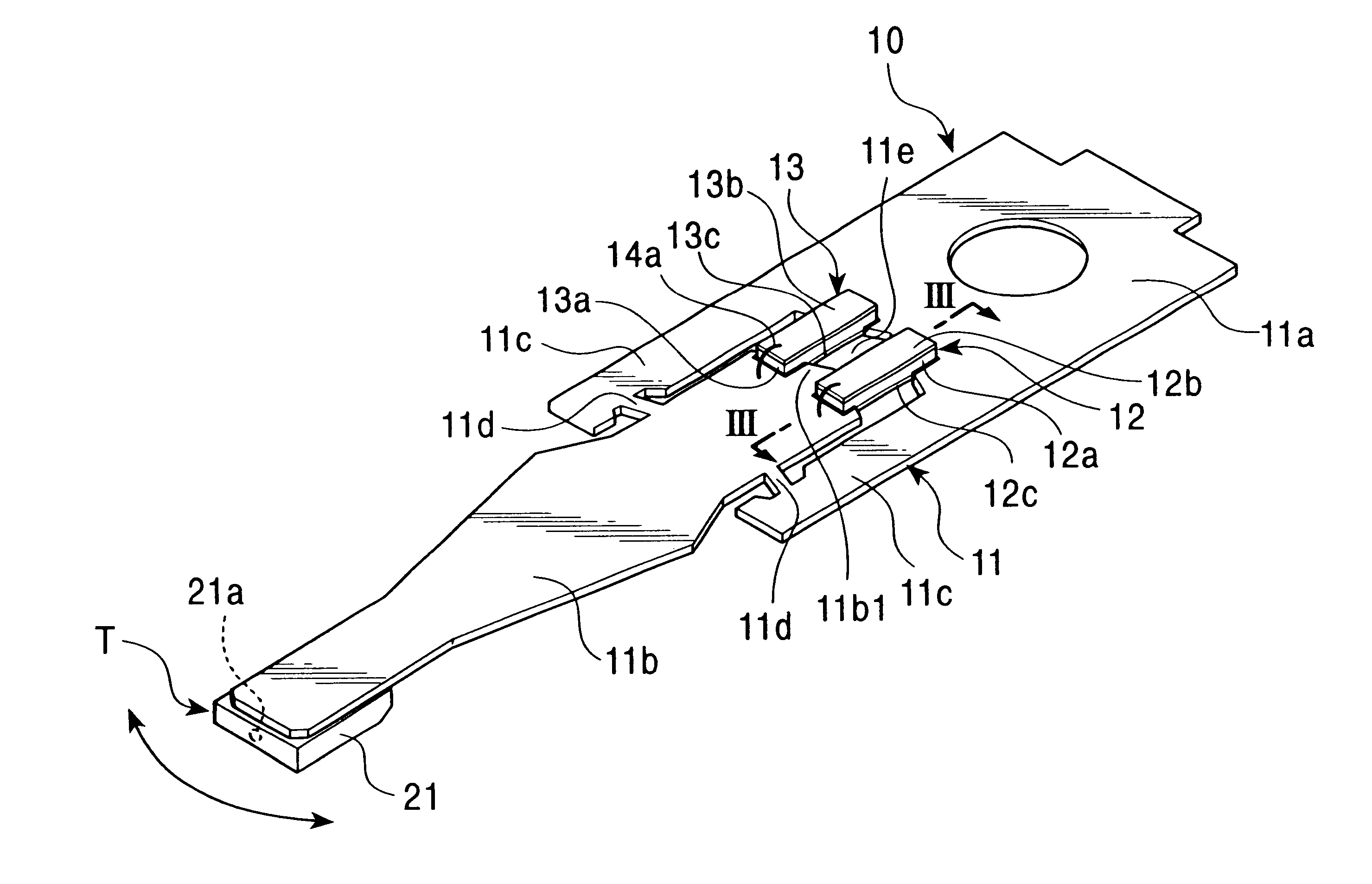
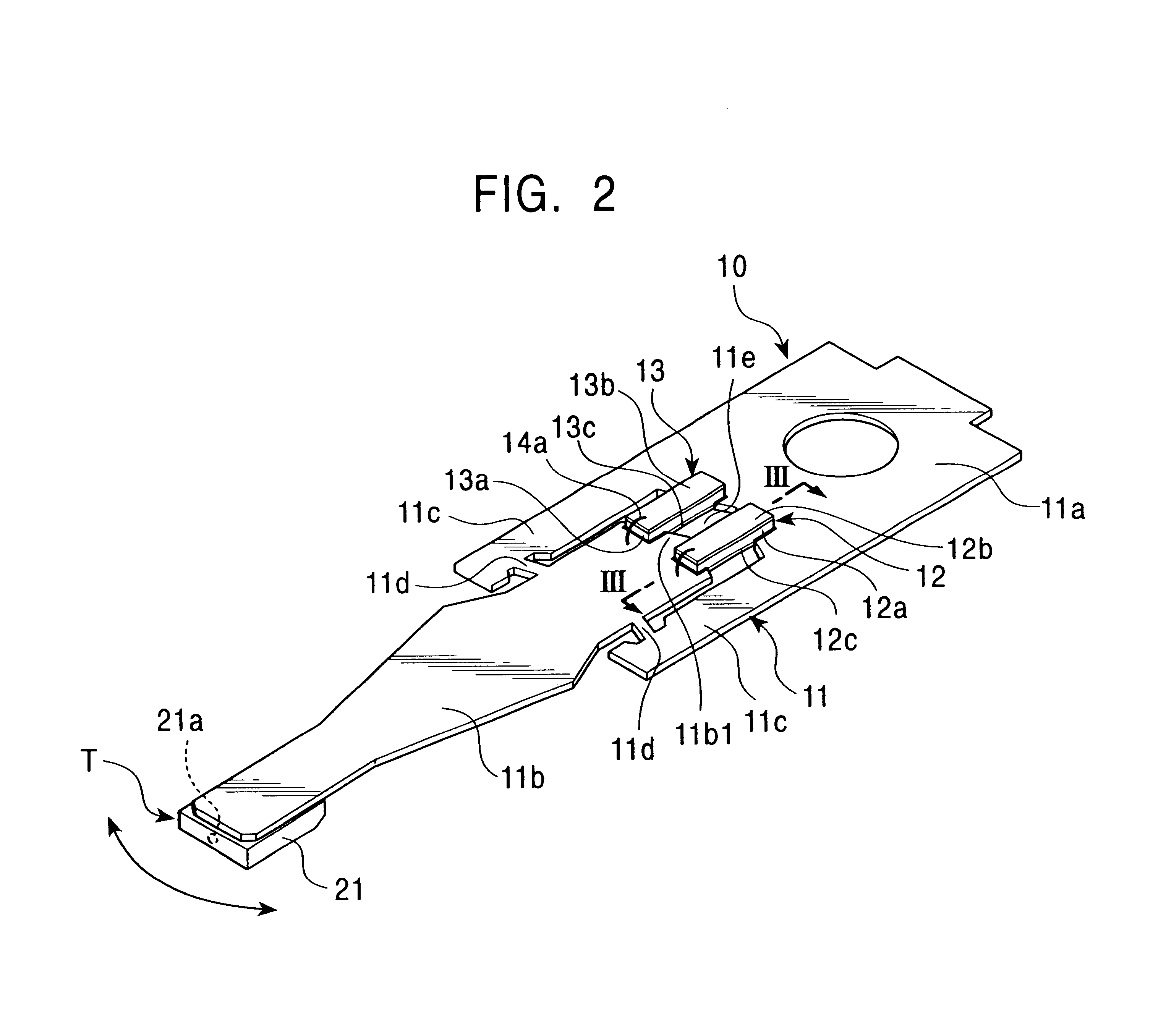
The slider was mounted at the tip of the load beam shown in FIG. 2, and a photocuring and thermosetting epoxy adhesive resin was coated on each of notches of the oscillating portion and the fixed base end of the load beam. Then, a piezoelectric element was mounted and bonded to the load beam by curing the adhesive resin by ultraviolet irradiation and heating to manufacture a magnetic head device.

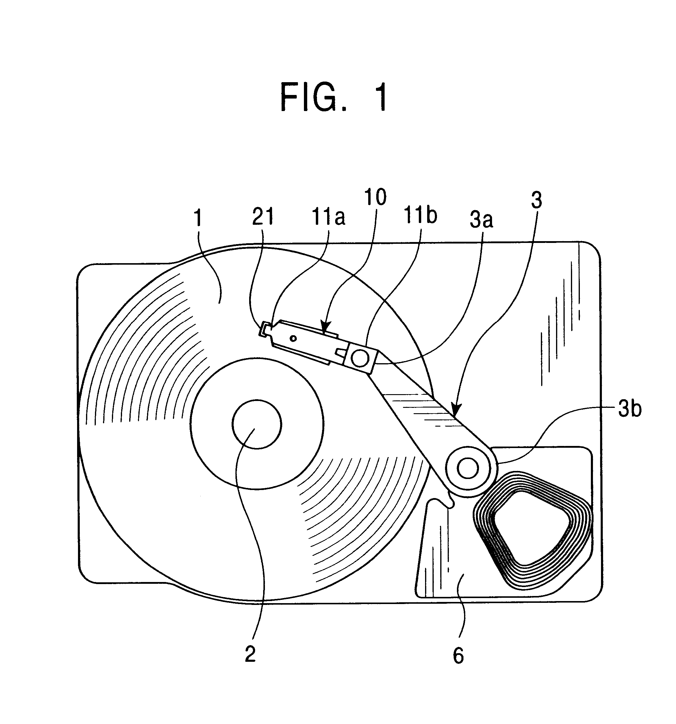
The thus-manufactured magnetic head device was incorporated into the hard disk device shown in FIG. 1, and a voltage of .+-.30 V (frequency 1 kHz) was applied to the piezoelectric element to perform the tracking operation by the slider. At this time, the displacement of the slider was measured. The results are shown in FIG. 4.

FIG. 4 shows the relationship between the displacement of...


PUM

PropertyMeasurementUnit
glass transition temperatureaaaaaaaaaa
Young's modulusaaaaaaaaaa

Abstract

The present invention provides a magnetic head device exhibiting a good bonded state of a piezoelectric element and a load beam, and excellent reliability. The magnetic head device includes a slider provided with a reproducing element for detecting a magnetic signal recorded on a recording medium, and a recording element for recording a magnetic signal on the recording medium, an elastic supporting member for supporting the slider, and piezoelectric elements mounted on the elastic supporting member, for distorting the elastic supporting member to change the position of the slider. The piezoelectric element and the elastic supporting member are bonded together with a photo-curing and thermosetting epoxy adhesive resin having a Young's modulus of 1 GPa or more at 25° C., and a glass transition temperature of 90° C. or more.

Description

1. Field of the InventionThe present invention relates to a magnetic head device comprising a piezoelectric element.2. Description of the Related ArtFIG. 6 is a plan view showing an example of a conventional hard disk device. The hard disk device shown in FIG. 6 comprises a magnetic disk 101, a spindle motor 102 for driving the magnetic disk 101 to rotate, a carriage 103, a load beam 104, a slider 105, and a voice coil motor 106. A magnetic head device schematically comprises the load beam 104 and the slider 105.The base end 104b of the load beam 104 serving as a supporting member is connected to the tip 103a of the carriage 103 comprising a rigid material, and the slider 105 is mounted at the tip 104a of the load beam 104 through a flexure (not shown in the drawing).The carriage 103 and the load beam 104 are driven in the radial direction of the magnetic disk 101 by the voice coil motor 106 to perform the seek operation of moving a reproducing element and recording element mounted ...

Claims


Application Information

Patent Timeline
Patent Type & Authority Patents(United States)
IPC IPC(8): G11B5/55G11B21/10G11B5/596G11B21/21
CPCG11B5/5552Y10T29/4903H01L2224/48091H01L2224/45144H01L2924/00014H01L2924/00
Inventor WATANABE, MITSURUSATO, HIDEZI
Owner TDK CORPARATION
Learn More