
Method and device for electronic cyclotronic resonance plasma deposit of carbon nanofibre layers in fabric form and resulting fabric layers

a carbon nanofibre and electronic cyclotron technology, applied in the manufacture of electrode systems, electric discharge tubes/lamps, tubes with screens, etc., can solve the problems of carbon fibre films, with the structure described above and without catalyst, that have never been obtained by the processes of the prior ar

Inactive Publication Date: 2004-09-07
COMMISSARIAT A LENERGIE ATOMIQUE ET AUX ENERGIES ALTERNATIVES
View PDF18 Cites 15 Cited by
  • Summary
  • Abstract
  • Description
  • Claims
  • Application Information

AI Technical Summary

Benefits of technology

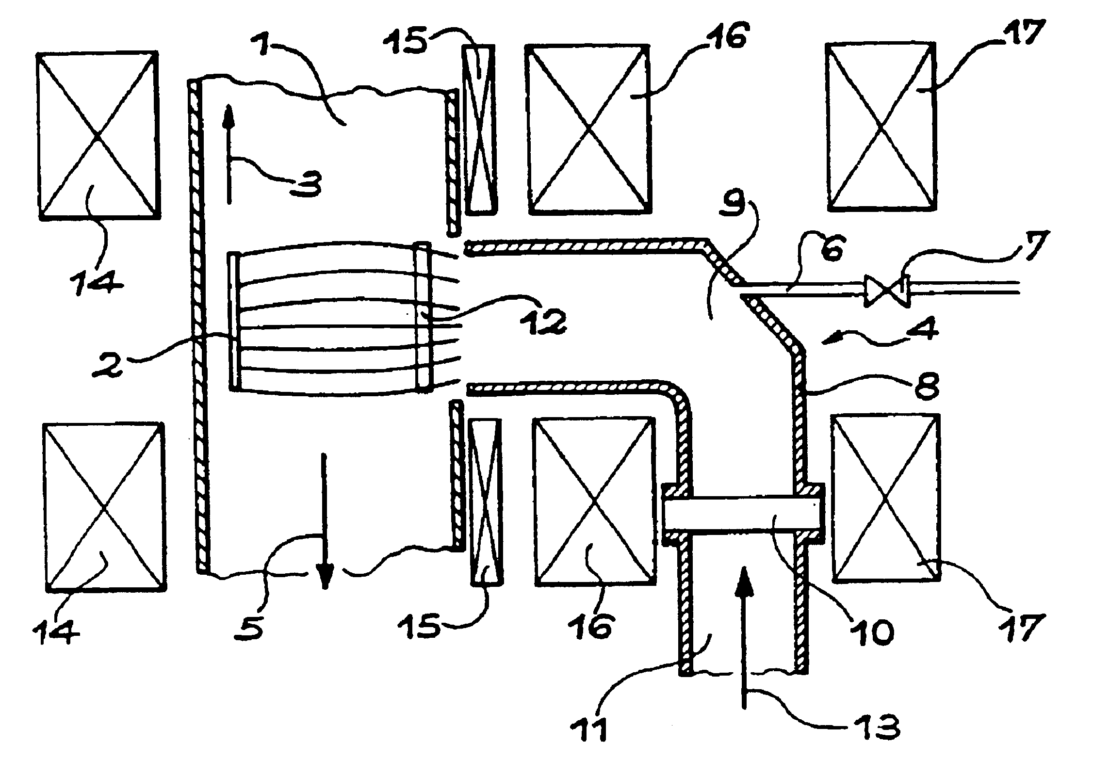
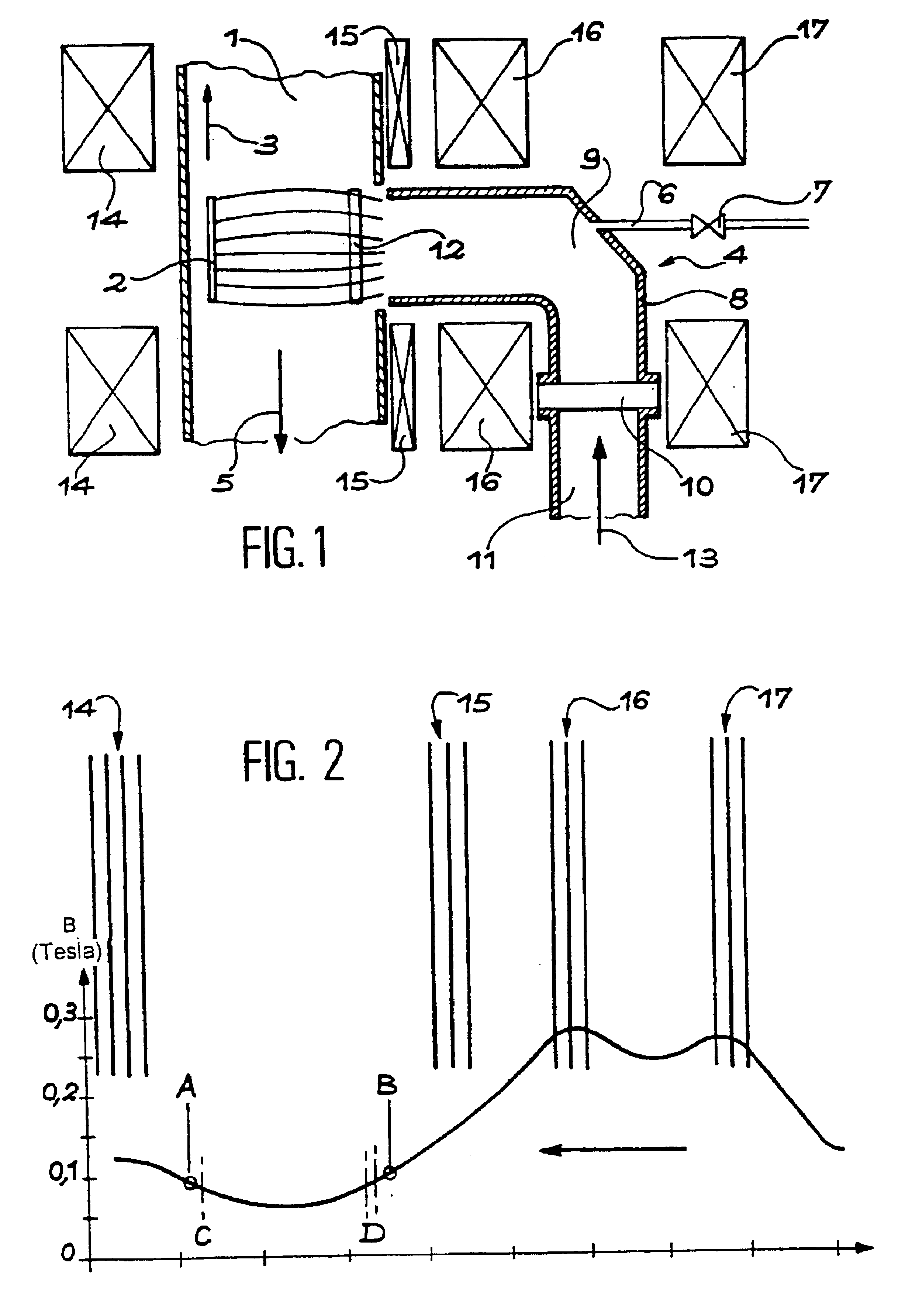
It is essentially the combination of this specific and confining ECR plasma source with this very low pressure that makes it possible, in the process according to the invention, to strongly dissociate the organic molecules in order to obtain films formed from webs of carbon nanofibres or nanotubes, or networks of interconnected carbon nanofibres or tubes, as in a spider's web.
In other words, this notable magnetic confinement makes it possible to increase the lifetime of the ions and the electrons that remain trapped in the magnetic mirror at the centre of the deposition chamber and along the field lines. The level of dissociation and ionisation of the molecules in the plasma is thus increased with the following types of electron collisions:
The low pressure increases the energy of the electrons and reduces re-combination.
This high mirror ratio makes it possible to make ionised particles (ions and electrons) diffuse towards the substrate under the effect of a decreasing gradient.
According to the invention, the pressure is maintained, preferably, at less than or equal to 8.10.sup.-5 mbar, in order to increase the energy of the electrons and reduce re-combination.

Problems solved by technology

In addition, none of the processes described above allow films of nanotubes to be prepared and, moreover, organised architectures of carbon nanofibres or nanotubes, such as webs of nanofibres or nanotubes directly from organic molecules and without a catalyst.
Films of carbon fibres, with the structure described above and without a catalyst, have never been obtained by the processes of the prior art.

Method used


Image

  • Method and device for electronic cyclotronic resonance plasma deposit of carbon nanofibre layers in fabric form and resulting fabric layers
  • Method and device for electronic cyclotronic resonance plasma deposit of carbon nanofibre layers in fabric form and resulting fabric layers
  • Method and device for electronic cyclotronic resonance plasma deposit of carbon nanofibre layers in fabric form and resulting fabric layers

Examples


example 1

In this example, the gas used is methane and the substrate is silicon heated to 640.degree. C.

The pressure within the deposition chamber or enclosure is 6.10.sup.-5 mbar.

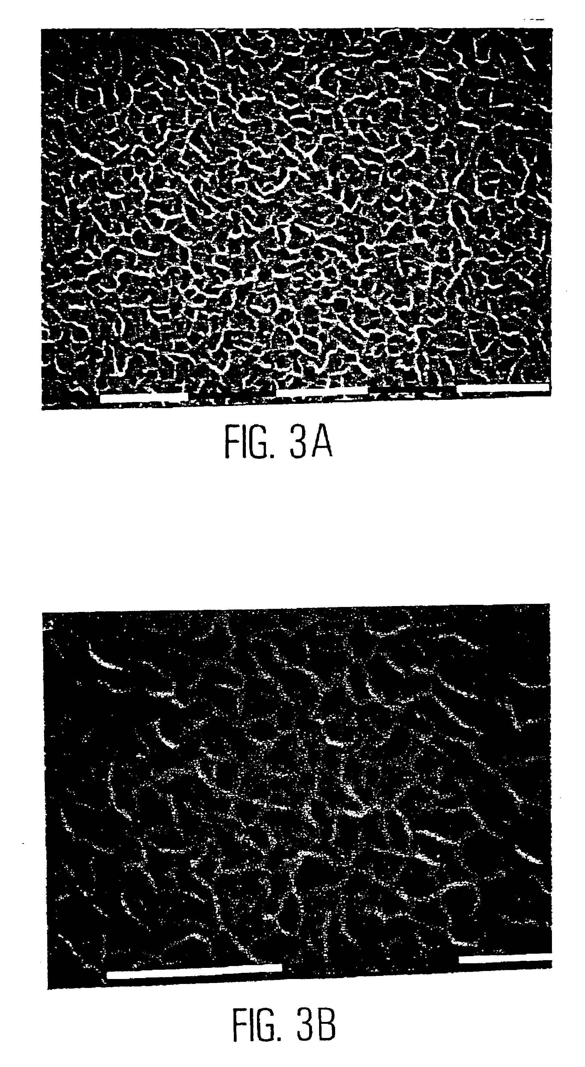
In this way, multi-layers of a web or network of interconnected carbon nanofibres or nanotubes with a fibre diameter of around 20 nm are obtained, which are like a spider's web, and whose average mesh size is less than 200 nm.

FIGS. 3A and 3B are scanning electron microscope (SEM) photographs of such multi-layers.

We have also removed a film (single layer) from the multi-layer deposit and spread it out on the grid of a transmission electron microscope (TEM): this type of operation highlights the solidity of the films obtained by the process according to the invention. The transmission electron microscope (TEM) photograph of the single layer is shown in FIG. 5.

example 2

In this example the gas used is methane and the substrate is borosilicate glass heated to 680.degree. C.

The pressure within the deposition chamber or enclosure is 8.10.sup.-5 mbar.

One thus obtains, in the same way as in Example 1, multi-layers of a web or network of interconnected carbon nanofibres or nanotubes with a fibre diameter of around 20 nm are obtained, which are like a spider's web, and whose average mesh size is near, or less than, 100 nm.

FIGS. 4A and 4B are scanning electron microscope (SEM) photographs of such multi-layers.

Apart from these SEM analyses and, if appropriate TEM analyses, other analyses may also be carried out. The results of all of the analyses carried out on the multi-layers or single layers in Example 1 and 2 are as follows:

Composition: carbon (several % of hydrogen were identified) (determined by ERDA--Elastic Recoil Detection Analysis)

TEM: diffraction photographs: the distance d (hkl) observed is 3.47 A, which corresponds more to a nanotube type struc...


PUM

PropertyMeasurementUnit
pressureaaaaaaaaaa
temperatureaaaaaaaaaa
frequencyaaaaaaaaaa

Abstract

Process and device for depositing, by electron cyclotron resonance plasma, a web of carbon nanofibres or nanotubes, on a substrate without a catalyst, by injection of a microwave power into a deposition chamber including a magnetic structure with a highly unbalanced magnetic mirror and at least one electron cyclotron resonance zone within the interior of the deposition chamber itself and opposite the substrate. Under a pressure of less than 10<-4 >mbar, ionization and / or dissociation of a gas containing carbon is induced in the magnetic mirror in the center of the deposition chamber, thus producing species that deposit on the substrate, which is heated. A resulting film, which may be on a substrate, can be formed from a web or a network of interconnected carbon nanofibres or nanotubes, like a spider's web, the film being exempt of a catalyst and a structure of several layers-a multi-layer structure-including at least two layers of a web of carbon nanofibres or nanotubes, as well as filters, electron accelerating or decelerating nanogrids and flat screens including such films or structures.

Description

DISCUSSION OF THE BACKGROUNDThe present invention concerns a process and a device for depositing, by electron cyclotron resonance plasma, films of carbon nanofibre webs.In addition, the invention concerns the films of web obtained in this manner.The technical field of the application may be defined, in a general manner, as that of depositing films of carbon on a substrate.Such films are, in particular, films of carbon that emit electrons, but we have also sought to develop processes whose purpose is to synthesise films of diamond, and profitably employ the mechanical, optical and electrical properties of diamond at temperatures generally between 400.degree. C. and 1,000.degree. C., or in order to make DLC ("Diamond Like Carbon") type carbon films, generally at low temperature (20.degree. C. to 400.degree. C.) and with a high level of C--C sp3 bonding, in particular for their mechanical properties.Such films are principally amorphous.More precisely, the present application is particu...

Claims


Application Information

Patent Timeline
Patent Type & Authority Patents(United States)
IPC IPC(8): H01J37/32H05H1/24H05H1/46C01B31/02C23C16/26H01J9/02H01J29/04H01J31/12
CPCB82Y10/00B82Y30/00H01J37/32192H01J37/32678H05H1/24Y10S977/843Y10S977/844
Inventor DELAUNAY, MARCSEMERIA, MARIE-NOELLE
Owner COMMISSARIAT A LENERGIE ATOMIQUE ET AUX ENERGIES ALTERNATIVES
Learn More