Compact turbocharger

a turbocharger and compact technology, applied in the field of turbochargers, can solve the problems of reducing the mechanical efficiency of turbochargers, and the differential speed between the sleeve bearing and the rotor is the very high rotative speed of the rotor, so as to reduce the thermal expansion of the shaft, and increase the protection of the anti-friction ball bearings

Inactive Publication Date: 2004-05-25
WOOLLENWEBER WILLIAM E
View PDF21 Cites 100 Cited by
  • Summary
  • Abstract
  • Description
  • Claims
  • Application Information

AI Technical Summary

Benefits of technology

In this invention, a turbocharger bearing housing forms a coolant water jacket with an inner bearing engaging portion that has two bearing engagement surfaces engaged with the outer races of two anti-friction ball bearings whose inner races carry the rotating shaft, turbine and compressor of the turbocharger. The anti-friction ball bearings are, preferably, angular contact ball bearings, and the two bearing engagement surfaces of the bearing housing are closely spaced, for example, a length of about the axial length of the compressor wheel or less, providing a turbocharger shaft of minimal length and substantially reducing the thermal expansion of the shaft. In the invention the coolant water jacket protects the anti-friction ball bearings from exposure to the extreme heat of the exhaust gas driven turbine, notwithstanding their increased proximity due to the shortened turbocharger shaft, and the bearing housing may be thinned, or otherwise adapted at the two bearing engagement surfaces for increased protection of the anti-friction ball bearings by the coolant water jacket.
The invention also overcomes the problems and complications of motor-assisted turbocharger systems by providing an economical combination of a motor-generator with a compact turbocharger that combines all the essential elements of a motor-assisted turbocharger in a single compact device. In the invention an external motor-generator is carried by the compact turbocharger and its motor is connected to the turbocharger rotor assembly by a permanent, solid connector and stays connected throughout the entire operating range of the turbocharger. The electronic motor-generator control is mounted on the motor housing and energizes the motor from battery power during the engine acceleration period up to approximately the torque peak speed; thereafter, the control changes to a generator mode when excess energy is available in the engine exhaust gas. Mounting the electronic control on the motor housing through which engine intake air is ducted allows a very short connection between motor and controller, and effective cooling of the control elements and the motor windings.

Problems solved by technology

However, the high rotational speed of the collar attached to the shaft resulted in a high thrust frictional loss which, in addition to the frictional losses of the sleeve bearings, resulted in a substantial total frictional loss for the complete bearing system.
Such high frictional losses substantially reduce the mechanical efficiency of turbochargers, and it has long been desirable to use anti-friction bearings.
In this bearing system, however, the differential speed between the sleeve bearing and rotor is the very high rotative speed of the rotor.
Since sleeve bearing frictional losses are proportional to the square of the differential rotating speed, this system has an inherent higher frictional loss than a full-floating sleeve bearing system.
The residual imbalance in the rotor forces the non-rotating cylinder to move orbitally, causing the mating surfaces to be subject to fretting.
Thus a solid film lubricant must be placed between the mating surfaces to mitigate the fretting problem; however, this problem remains an inherent disadvantage with this type of non-rotating cylinder system and contributes to a limited service life in the field.
Oil leakage in turbochargers has been a persistent problem and a completely satisfactory solution has yet to be found.
The small ring seals now used in commercial turbochargers to confine the bearing lubrication must allow some running clearance to eliminate friction and wear; thus, they cannot be totally leak free during some engine operating conditions.
For example, when the engine is running at low idle speeds and when a vacuum exists in the air intake system due to the pressure drop across the air cleaner, there is a tendency for oil leakage to occur into the compressor chamber which can subsequently be carried into the engine air intake manifold.
However, prior motor-assisted turbocharger systems have suffered from certain deficiencies and complications.

Method used


Image

  • Compact turbocharger
  • Compact turbocharger
  • Compact turbocharger

Examples


Embodiment Construction

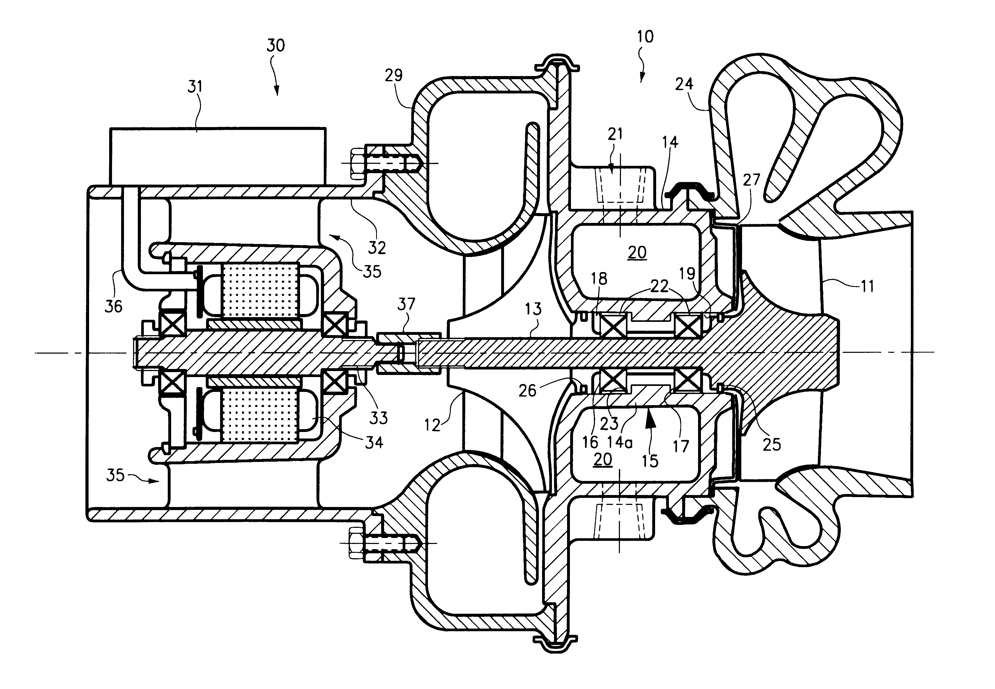
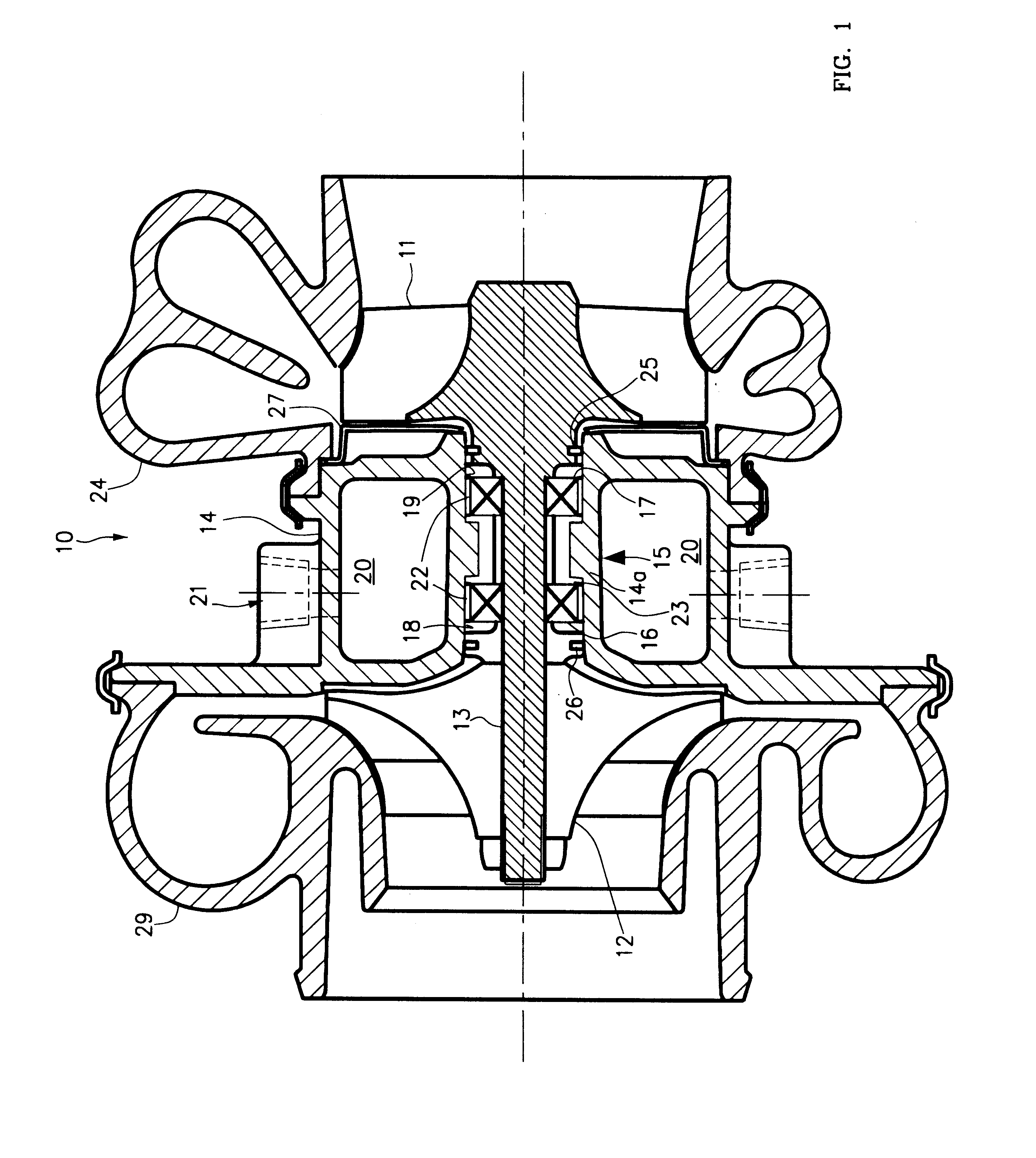
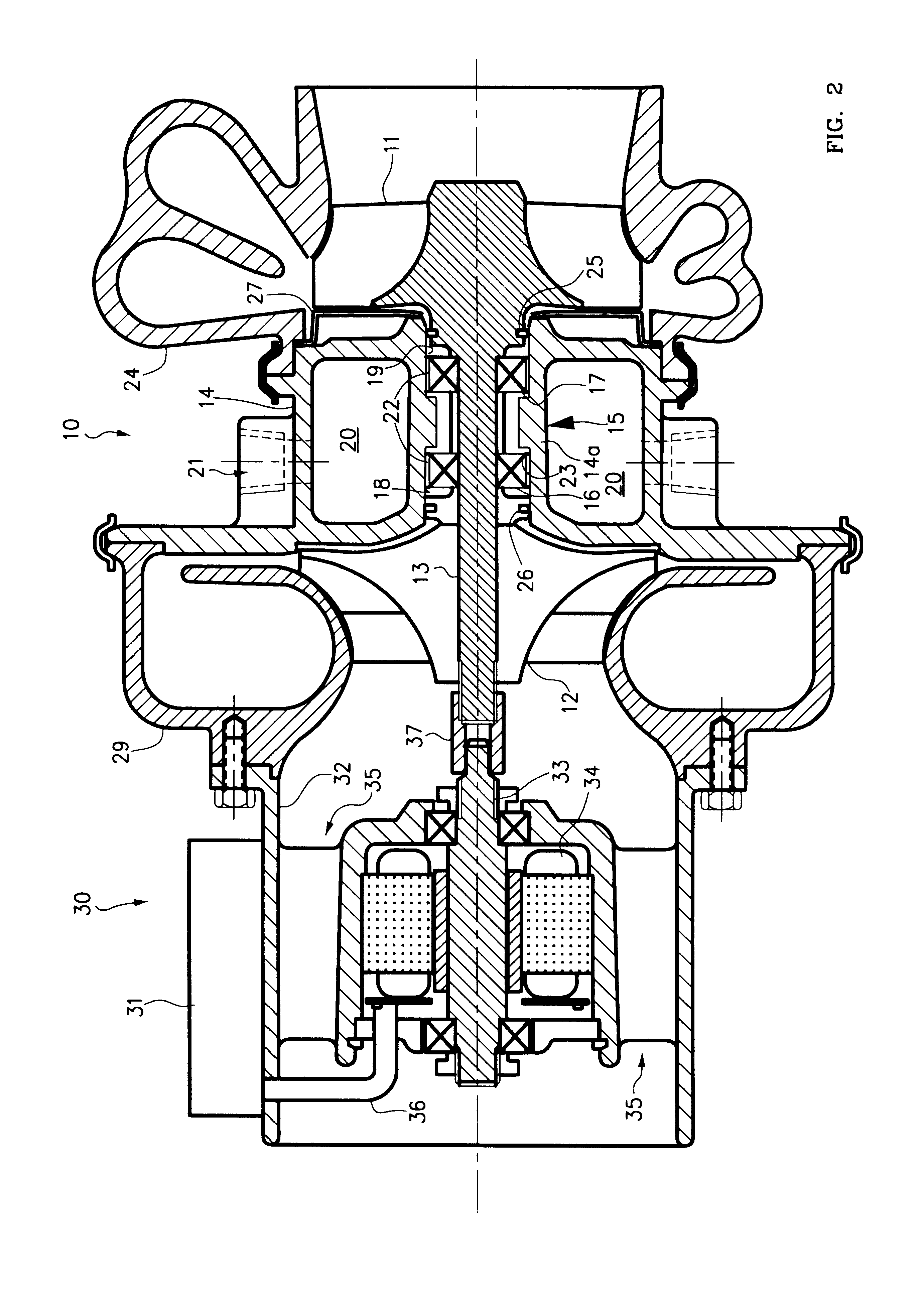
The invention, as illustrated in FIG. 1, provides a compact turbocharger 10 including an exhaust gas-driven turbine wheel 11 and a compressor wheel 12 on a rotatable shaft 13 carried by a bearing housing 14 and bearing system 15 that includes a pair of anti-friction ball bearings 16, 17.

The bearing housing 14 comprises an inner bearing-engaging portion 14a with two bearing engagement surfaces 18, 19 for engagement with the outer races of the anti-friction ball bearings 16, 17. As illustrated in FIG. 1, the bearing housing 14 forms a coolant water jacket 20 for cooling the two bearing engagement surfaces 18, 19 and maintaining satisfactory operating temperatures of the anti-friction ball bearings 16, 17. The bearing housing 14 has an inlet 21 for coolant that may be connected with the coolant system of an internal combustion engine so engine coolant may be circulated through the coolant water jacket 20 of the turbocharger. Thus, the bearing housing 14 contains a coolant water jacket ...


PUM


Abstract

A turbocharger comprising two closely spaced ball bearings that does not require lubricating oil from an engine. The bearing housing forms a cooling jacket with two bearing engagement surfaces engaged with the outer races of the ball bearings through an intermediate radial spring. Closely spacing the ball bearings provides a rotor shaft of minimal length. In addition, an external motor-generator may be by mounted on the turbocharger, with the motor rotor solidly connected to the turbocharger rotor. In such an assembly, an electronic control is energizes the motor from battery power during acceleration up to approximately torque peak speed; thereafter, the control changes to a generator mode when there is excess energy in the engine exhaust gas.

Description

I. TECHNICAL FIELD OF THE INVENTIONThis invention relates to turbochargers that have rotor assemblies that rotate at high speed and are used on internal combustion engines where the turbine component of the rotor is driven by high temperature exhaust gas.II. BACKGROUND ARTTurbochargers are produced currently in the millions per year for use on both gasoline and diesel engines. Small units used on passenger car diesel and gasoline engines have been designed to reduce the rotor inertia and minimize turbocharger rotor lag during engine acceleration.Much effort was expended in the early years of turbocharger development to produce a bearing system that exhibited sufficient durability to make a small size turbocharger commercially viable. Bearing systems for small turbochargers run at very high speeds, some exceeding 200,000 rpm, must be capable of mass production manufacturing methods, be low in cost, and easily serviced in the field.Research and development during the 1960's resulted i...

Claims


Application Information

Patent Timeline
Patent Type & Authority Patents(United States)
IPC IPC(8): F01D15/00F01D15/10F01D25/16F02B37/10F16C37/00F02B39/02F02B37/04F02B39/10F02C7/06F04D25/02F04D25/04F04D29/04F04D29/056F04D29/059
CPCF01D15/10F01D25/16F02B37/025F02B37/10F02B39/10F02C7/06F04D29/0566F04D29/059F04D25/024F16C37/007Y02T10/144F05D2220/40F16C2360/24H02K5/1732H02K7/14H02K9/06H02K11/33Y02T10/12
Inventor WOOLLENWEBER, WILLIAM E.
Owner WOOLLENWEBER WILLIAM E
Why Eureka
Try Eureka