
Grain conveyor with high lift belt

a conveyor belt and grain technology, applied in the field of belt conveyors, can solve the problems of limited vertical lift capability, fracture and damage valuable seeds, and ground space limitations, and achieve the effect of high vertical lift, minimal length and high vertical li

Inactive Publication Date: 2013-07-04
CRUSTBUSTERSPEED KING
View PDF1 Cites 14 Cited by
  • Summary
  • Abstract
  • Description
  • Claims
  • Application Information

AI Technical Summary

Benefits of technology

The patent is for a belt conveyor that has special features to prevent materials from flowing backward. It also has a bottom return section with support elements for the belt. The belt lugs form a constant surface for low friction support by the support elements. These features improve the conveyor's performance and stability.

Problems solved by technology

While these have been widely successful, there has always been limitations in vertical lift capability.
While auger conveyors are useful for lift capability, augers can fracture and damage valuable seed.
Naturally, when these ultra long conveyors are used in farm yards and seed distributor yards, ground space limitations become apparent.
Additionally, ultra long conveyors are difficult to transport over roads.
Naturally, these individually attached lugs create significant expense in the production of the belt.
Moreover, the more uneven the surface of the belt as created by the use of attached lugs or deeply embossed patterns, the greater is the roughness or chatter of the belt upon its return in the conveyor.
The roughness and severe vibration in the belt return section can shear the belt lugs and can lead to material failure of the components of the conveyor and belt; quite literally, the conveyor can shake itself apart.

Method used


Image

  • Grain conveyor with high lift belt
  • Grain conveyor with high lift belt
  • Grain conveyor with high lift belt

Examples


Embodiment Construction

[0020]As required, a detailed embodiment of the invention is disclosed herein; however, the invention is not intended to be limited in scope or interpretation to any particular embodiment except insofar as required under law. Rather, the disclosure embodiment is only an example, and other embodiments within the scope of the invention may be conceived after reading the disclosure or may be developed subsequently. This disclosure is intended solely as a basis for the claims, the invention being as set forth in the claims.

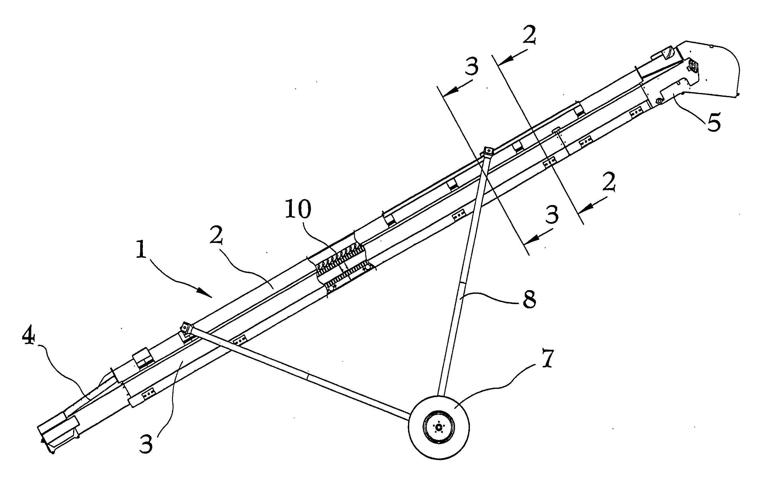
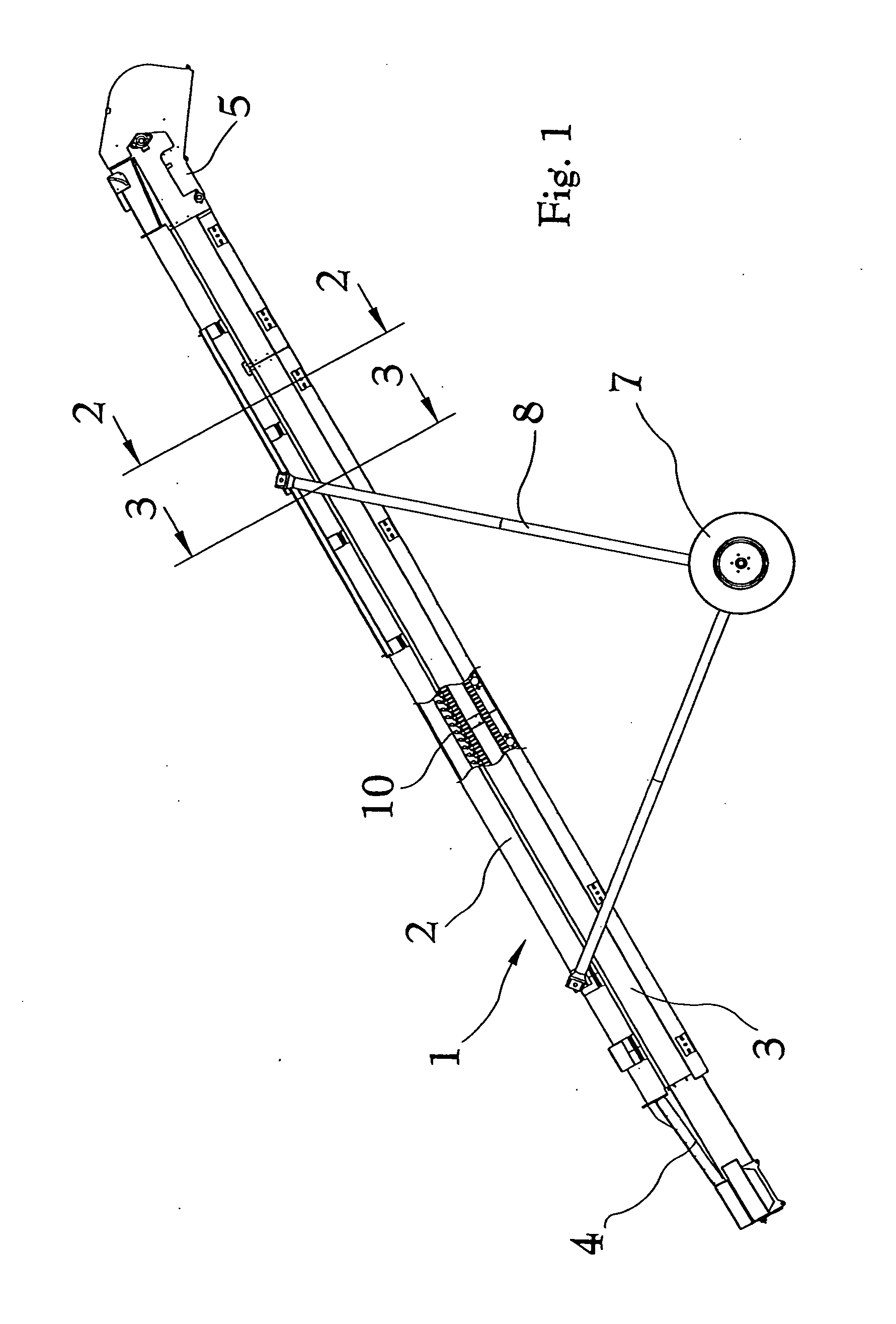
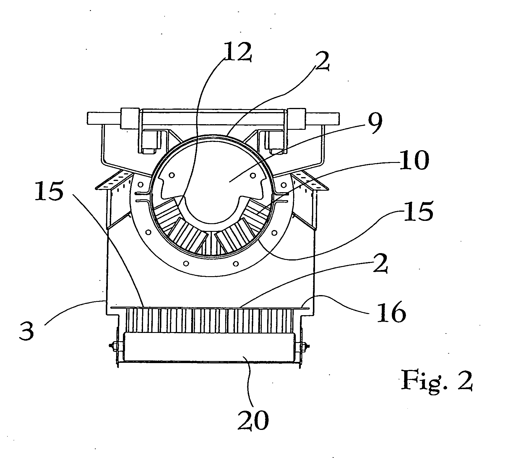
[0021]The reference numeral 1, FIG. 1, generally indicates a conveyor embodying the present invention. The conveyor 1 has an enclosed housing 2 comprising the conveyed section and a return section 3 there below. The conveyor 1 has an infeed end 4 and a discharge head 5. A conveyor drive is provided which may be of various known power units. Wheels 7 and variable height mounting structure 8 allow positioning and transport of the conveyor 1. In the illustrated example, ...


PUM


Abstract

A belt conveyor for grain or other granular materials has an enclosed housing, a bottom return, an infeed end and a discharge head. The conveyor uses a special high angle lift belt with projecting lugs of approximately two inches high and having cooperating angled elements that form material receiving pockets. The lugs are arrayed on the belt in meshing relationship so that as the belt curls laterally within the housing, the lugs prevent backflow of materials at least up to a forty degree angle when the conveyor is running. The bottom return section of the conveyor has a plurality of belt supporting rollers extending transversely across the return section. The belt lugs are also arranged so that upper ends of the lugs form a longitudinally and transversely continuous supportive surface for low friction running support by the belt return rollers.

Description

BACKGROUND OF THE INVENTION[0001]1. Field of the Invention[0002]The present invention relates to belt conveyors for handling grain, fertilizer and other granular or particulate agricultural and industrial products. Used by farm operators and product distributors, these conveyors move product between containers, such as from seed boxes into bins. These conveyors are often used in settings where there is limited or tight ground space and the product must be lifted to substantial height, such as from ground level into a twenty foot high bin.[0003]2. Description of the Related Art[0004]Belt conveyors have been used in the agricultural industry for many years, many of them pioneered by the owner herein. While these have been widely successful, there has always been limitations in vertical lift capability. While auger conveyors are useful for lift capability, augers can fracture and damage valuable seed. Using a flat belt, lift has generally been restricted to 25 to 26 degrees, with the r...

Claims


Application Information

Patent Timeline
Patent Type & Authority Applications(United States)
IPC IPC(8): B65G15/42B65G15/08
CPCA01D87/02B65G41/00B65G15/42B65G15/40
Inventor FANSHIER, BENJAMINMARLER, RONALD L.
Owner CRUSTBUSTERSPEED KING
Learn More